
Inspection/Replacement
- Make
- Rover
- Model
- 600 Rover 600 Repair Manual - Volumes 1 and 2 - 2nd Edition
- Section
- Repairs › Inspection/Replacement
ClutchInspection/Replacement
Inspection/Replacement
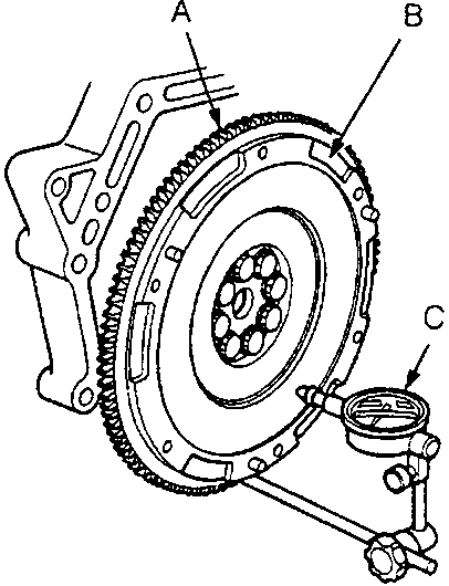
- Ring gear
- Flywheel
- Dial indicator
- Inspect the ring gear teeth of the flywheel for wear and damage.
- Inspect the clutch disc mating surface on the flywheel for wear, cracks and burning.
- Measure the flywheel runout using a dial indicator through at least two full turns. Push the flywheel towards the engine to take up the crankshaft thrust washer clearance.
Note: The runout can be measured with engine installed.
Standard (New): 0.05 mm max.
Service Limit: 0.15 mm.
If the runout exceeds the service limit, replace the flywheel.
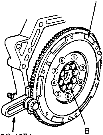
- Flywheel
- Mounting bolt
- Install the special tool as shown.
- Remove the eight flywheel mounting bolts in a crisscross pattern in several steps as shown, and remove the flywheel.
- Install the flywheel in the reverse order of removal.
Parts & tools for this job For Rover 600
- PARTClutch kitSearch: Rover 600 clutch kit
- TOOLClutch alignment toolSearch: clutch alignment tool
- FLUIDGear oilSearch: Rover 600 manual gearbox oil
Links open Amazon search results in a new tab. As an Amazon Associate I earn from qualifying purchases.