
1. Connectors with covers
- Make
- Rover
- Model
- 600 Rover 600 Repair Manual - Volumes 1 and 2 - 2nd Edition
- Section
- Information › 1. Connectors with covers
Despite the many different appearances and colours connectors can be grouped into three categories.
1. Connectors with covers
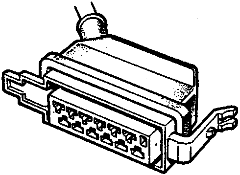
86M 2549
Examples of this connector are found on ECU's and fuel injector connectors, etc.
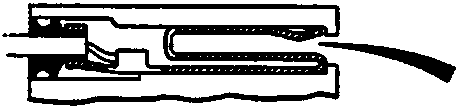
86M 2550
Insert test probe here
For testing at these style of connectors bring the tester probe into contact with the terminal from the connector side of wire harness connectors. For female connectors, insert the special probe carefully.
Note: Do not attempt to remove rubber seal and probe into the rear of the connector as damage to the seal will occur.
2. Sealed connectors (with individually sealed wires)
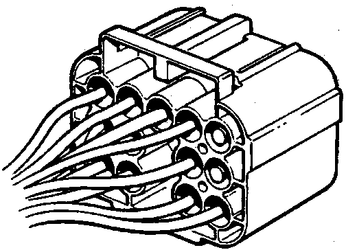
86M 2551
Examples of this connector are found on MEMS ECU's and relay modules, etc.
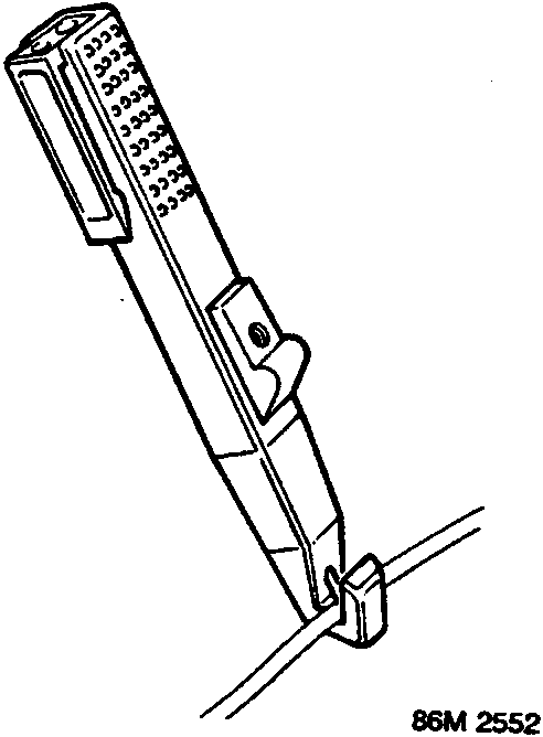
86M 2552
For testing at these style of connectors use the hook and pin probe. Carefully separate out the wire for testing, bring the probe over the wire to be tested. Release probe carefully and gradually puncture the wire insulation to avoid necessary damage the insulation or wire strands.
Check that the wire colour matches the pin/cavity number. If it does not, rectify this first as probing will not find the fault
Note: Do not attempt to carry out this test with any other hook and pin probe than the Rover special tool.
Parts & tools for this job For Rover 600
- TOOLDigital multimeterSearch: automotive digital multimeter
- PARTAssorted fuse kitSearch: car fuse assortment kit
- TOOLWire crimper and connector kitSearch: wire crimper connector kit
Links open Amazon search results in a new tab. As an Amazon Associate I earn from qualifying purchases.