
86M 1920
- Make
- Rover
- Model
- 600 Rover 600 Repair Manual - Volumes 1 and 2 - 2nd Edition
- Section
- Information › 86M 1920
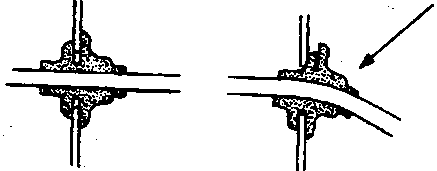
86M 1920
A Not good
- Seat grommets in their grooves properly.
Testing and Repairs
- Do not use wires or harnesses with broken insulation. Replace them or repair them by wrapping the break with electrical tape.
- After installing parts, make sure that no wires are pinched under them.
- When using electrical test equipment, follow the manufacturer's instructions and those described in this manual.
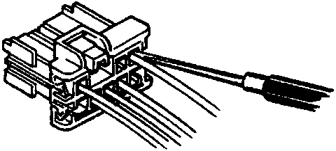
86M 1921
- If possible, insert the probe of the tester from the wire side (except waterproof connector).

86M 1922
- Use a probe with a tapered tip.
Five - step Fault Finding
1. Verify The Complaint
Turn on all the components in the problem circuit to verify the customer complaint. Note the symptoms. Do not begin disassembly or testing until you have narrowed down the problem area.
2. Analyse The Schematic
Look up the schematic for the problem circuit. Determine how the circuit is supposed to work by tracing the current paths from the power feed through the circuit components to earth. If several circuits fail at the same time, the fuse or earth is a likely cause.
Based on the symptoms and your understanding of the circuit operation, identify one or more possible causes of the problem.
3. Isolate The Problem By Testing The Circuit
Make circuit tests to check the diagnosis you made in step 2. Keep in mind that a logical, simple procedure is the key to efficient fault finding. Test for the most likely cause of failure first. Try to make tests at points that are easily accessible.
4. Fix The Problem
Once the specific problem is identified, make the repair. Be sure to use proper tools and safe procedures.
5. Make Sure the Circuit Works
Turn on all components in the repaired circuit in all modes to make sure you've fixed the entire problem. If the problem was a blown fuse, be sure to test all of the circuits on the fuse. Make sure no new problems turn up and the original problem does not recur.
Original page
Parts & tools for this job For Rover 600
- TOOLDigital multimeterSearch: automotive digital multimeter
- PARTAssorted fuse kitSearch: car fuse assortment kit
- TOOLWire crimper and connector kitSearch: wire crimper connector kit
Links open Amazon search results in a new tab. As an Amazon Associate I earn from qualifying purchases.