
Information: Special tools
- Make
- Rover
- Model
- 600 Rover 600 Repair Manual - Volumes 1 and 2 - 2nd Edition
- Section
- Information › Special tools
ElectricalSpecial tools
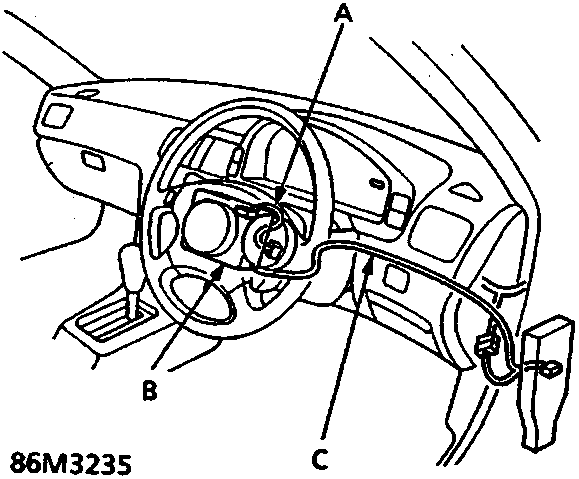
SRS Type II
- A SRS unit sub-harness
- B SRS unit (built-in sensors)
- C SRS main harness - YELLOW
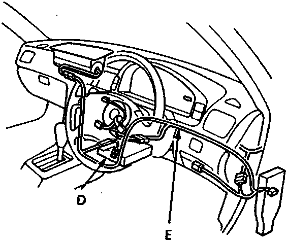
SRS Type III
- D SRS unit (built-in sensors)
- E SRS main harness - YELLOW
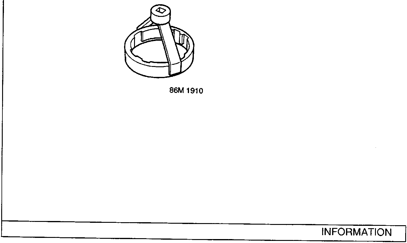
SPECIAL TOOLS
| No. | Honda Number | Rover Number | Description |
|---|---|---|---|
| 1 | 07GAC-SE0020A | 18G1595 | Fuel Sender Spanner |
The tools illustrated in this section are Honda tools, and Rover do not always have an equivalent. Where an equivalent Rover tool is available, it may not be visually identical to the Honda tool.
Parts & tools for this job For Rover 600
- TOOLDigital multimeterSearch: automotive digital multimeter
- PARTAssorted fuse kitSearch: car fuse assortment kit
- TOOLWire crimper and connector kitSearch: wire crimper connector kit
Links open Amazon search results in a new tab. As an Amazon Associate I earn from qualifying purchases.