
Caution:
- Make
- Rover
- Model
- 600 Rover 600 Repair Manual - Volumes 1 and 2 - 2nd Edition
- Section
- Information › Caution:
Engine management system – PGM-FiCaution:
Some models of the Rover 600 include a driver’s side airbag, located in the steering wheel hub, as part of a supplemental restraint system (SRS). Information necessary to safely service the SRS is included in this Repair Manual. Items marked (*) on the contents page include, or are located near, SRS components. Servicing, disassembling or replacing these items will require special precautions and tools, and should therefore be done only by an authorised ROVER dealer
WARNING:
- To avoid rendering the SRS inoperative, which could, in the event of a severe frontal collision, lead to personal injury or death, all maintenance on this system must be performed by an authorised ROVER dealer.
- Improper maintenance, including incorrect removal and installation of the SRS, and the use of the wrong parts, could lead to personal injury caused by unintentional activation of the airbag.
- All SRS electrical wiring harnesses are covered with yellow outer insulation. Related components are located in the steering column, the dashboard, and behind the dashboard lower cover. Do not use electrical test equipment on these circuits.
- Servicing, disassembling or replacing adjacent to the steering wheel, under the dash, or related to the wiring harnesses adjacent to the under – dash fuse/relay box may affect the SRS and must therefore be performed by an authorised ROVER dealer
CAUTION:
- All SRS electrical wiring harnesses are covered with yellow outer insulation.
- Replace the entire affected SRS harness assembly if it has an open circuit or damaged wiring.
- Before disconnecting the SRS wiring harness, turn the ignition switch off, disconnect the negative and positive battery cables, and wait at least three minutes.
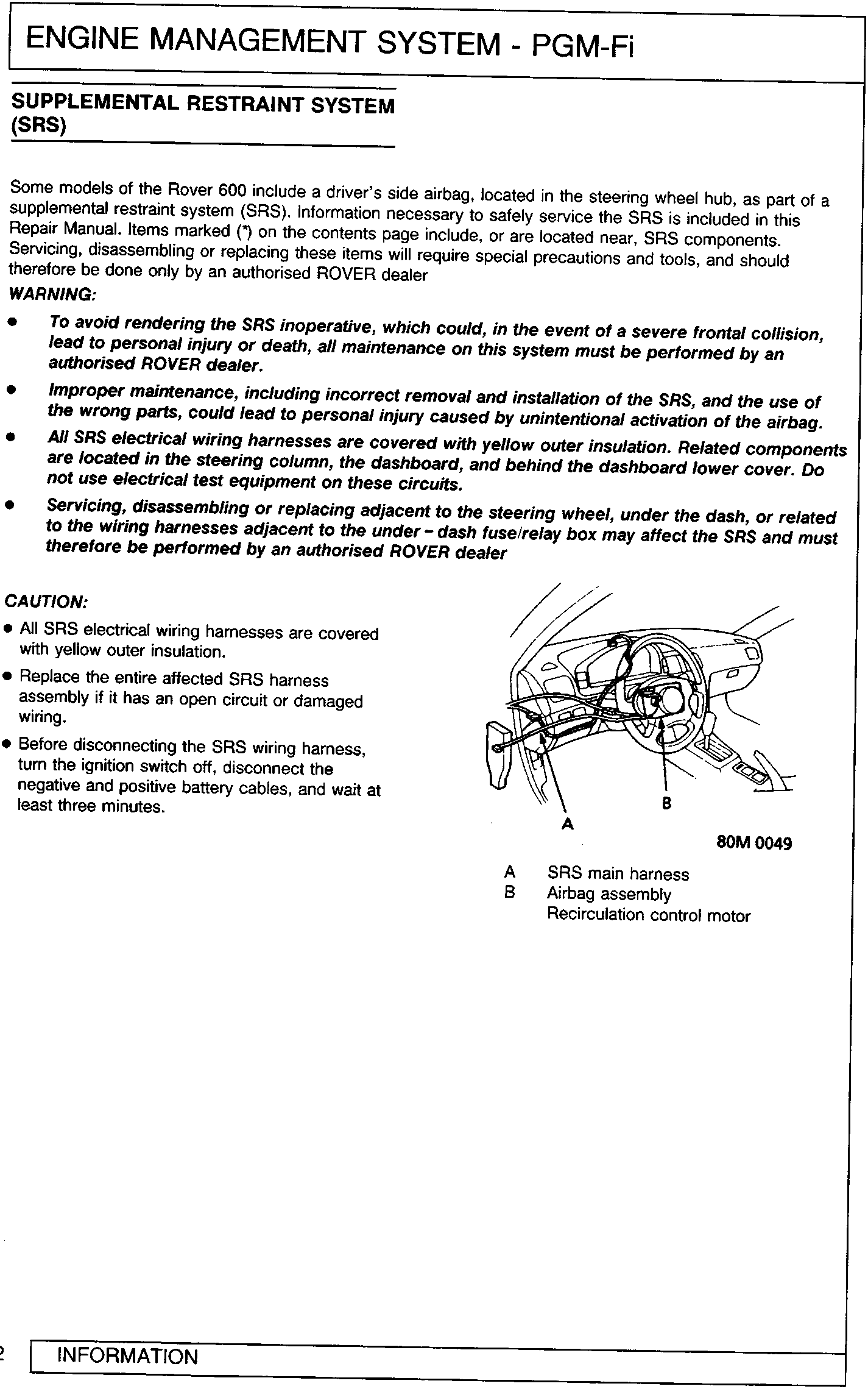
80M 0049
- A SRS main harness
- B Airbag assembly
- Recirculation control motor
Parts & tools for this job For Rover 600
- PARTEngine gasket setSearch: Rover 600 engine gasket set
- TOOLTorque wrenchSearch: 3/8 inch torque wrench
- TOOLFeeler gauge setSearch: feeler gauge set
Links open Amazon search results in a new tab. As an Amazon Associate I earn from qualifying purchases.