
Throttle body
- Make
- Rover
- Model
- 600 Rover 600 Repair Manual - Volumes 1 and 2 - 2nd Edition
- Section
- Information › Throttle body
Engine management system – PGM-FiThrottle body
Throttle body
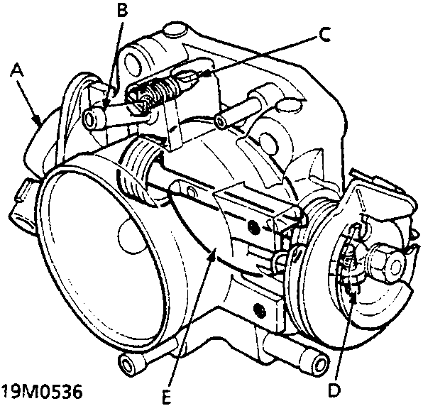
| A | Throttle Position (TP) sensor | D | Throttle stop screw |
| B | EVAP control port | E | Throttle valve |
| C | Idle adjusting screw |
The throttle body is of the single-barrel side-draft type. The lower portion of the throttle valve is heated by engine coolant which is fed from the cylinder head. The idle adjusting screw which increases/decreases bypass air and the evaporative emission (EVAP) control canister port are located on the top of the throttle body.
Note: The throttle stop screw is preset in the factory and is not adjustable.
Parts & tools for this job For Rover 600
- TOOLTrim removal tool kitSearch: trim removal tool kit
- PARTTouch-up paintSearch: Rover touch up paint
- PARTPanel clip assortmentSearch: Rover panel clips assortment
Links open Amazon search results in a new tab. As an Amazon Associate I earn from qualifying purchases.