
Vacuum Connections
- Make
- Rover
- Model
- 600 Rover 600 Repair Manual - Volumes 1 and 2 - 2nd Edition
- Section
- Information › Vacuum Connections
Engine management system – PGM-FiVacuum Connections
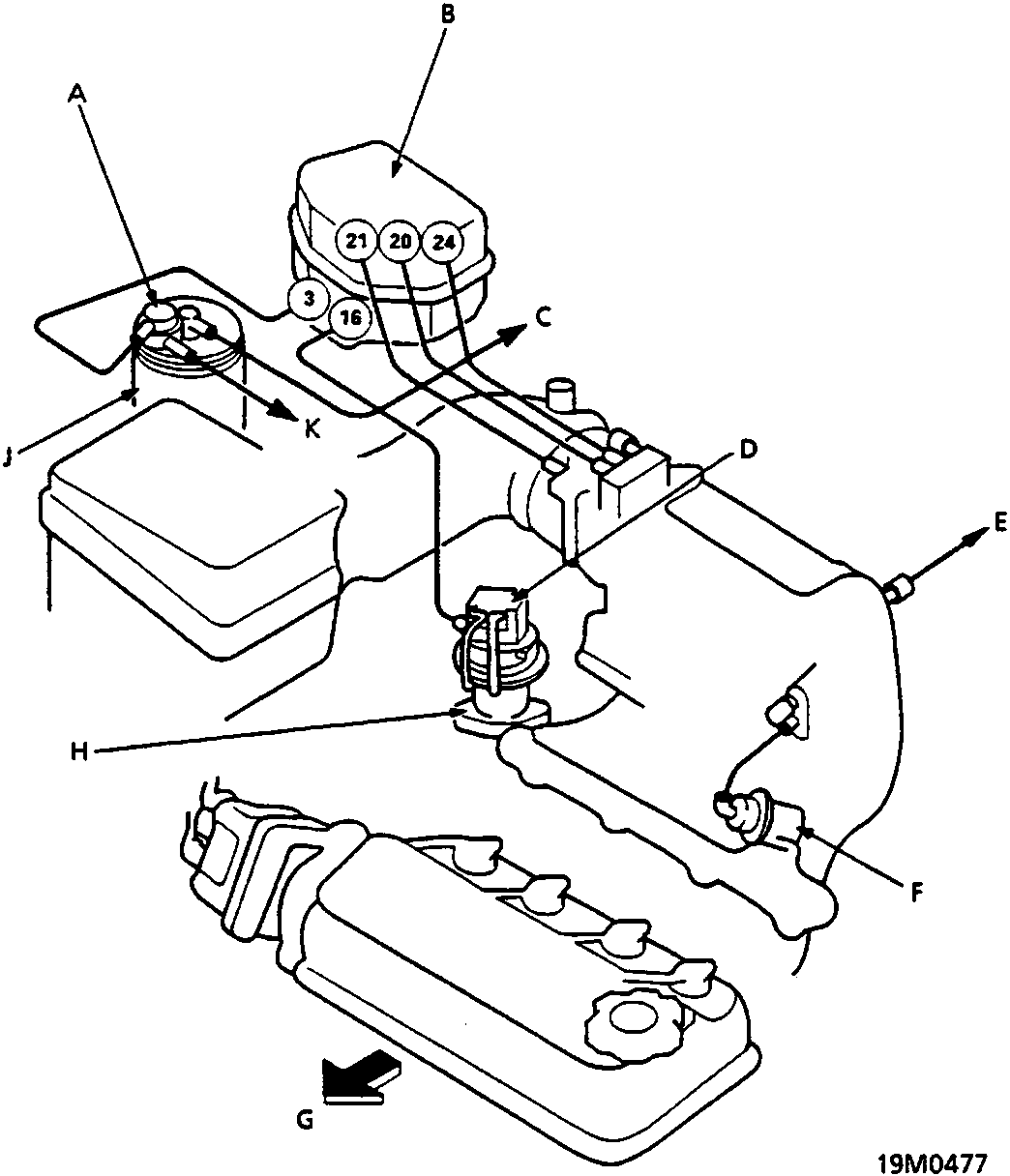
Vacuum Connections
| A Evaporative Emission (EVAP) purge control diaphragm valve | F Fuel pressure regulator |
| B Control box | G Front of vehicle |
| C To Evaporative Emission (EVAP) two way valve | H Exhaust Gas Recirculation (EGR) valve |
| D Exhaust Gas Recirculation (EGR) valve lift sender | J Evaporative Emission (EVAP) control canister |
| E To engine mount control solenoid valve (A/T only) | K To throttle body |
Parts & tools for this job For Rover 600
- PARTEngine gasket setSearch: Rover 600 engine gasket set
- TOOLTorque wrenchSearch: 3/8 inch torque wrench
- TOOLFeeler gauge setSearch: feeler gauge set
Links open Amazon search results in a new tab. As an Amazon Associate I earn from qualifying purchases.