
Vacuum Control System Schematic
- Make
- Rover
- Model
- 600 Rover 600 Repair Manual - Volumes 1 and 2 - 2nd Edition
- Section
- Information › Vacuum Control System Schematic
Engine management system – PGM-FiVacuum Control System Schematic
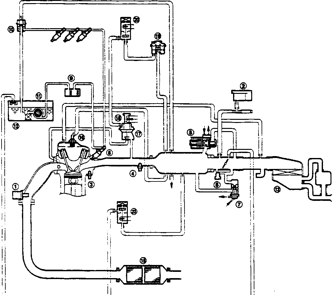
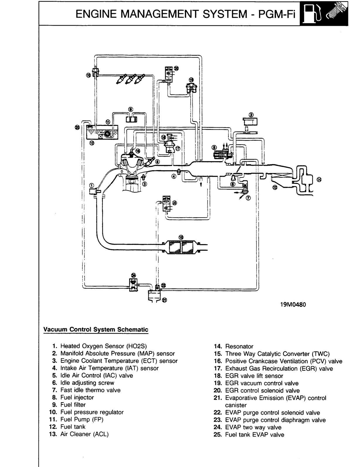
19M0480
Vacuum Control System Schematic
- 1. Heated Oxygen Sensor (HO2S)
- 2. Manifold Absolute Pressure (MAP) sensor
- 3. Engine Coolant Temperature (ECT) sensor
- 4. Intake Air Temperature (IAT) sensor
- 5. Idle Air Control (IAC) valve
- 6. Idle adjusting screw
- 7. Fast idle thermo valve
- 8. Fuel injector
- 9. Fuel filter
- 10. Fuel pressure regulator
- 11. Fuel Pump (FP)
- 12. Fuel tank
- 13. Air Cleaner (ACL)
- 14. Resonator
- 15. Three Way Catalytic Converter (TWC)
- 16. Positive Crankcase Ventilation (PCV) valve
- 17. Exhaust Gas Recirculation (EGR) valve
- 18. EGR valve lift sensor
- 19. EGR vacuum control valve
- 20. EGR control solenoid valve
- 21. Evaporative Emission (EVAP) control canister
- 22. EVAP purge control solenoid valve
- 23. EVAP purge control diaphragm valve
- 24. EVAP two way valve
- 25. Fuel tank EVAP valve
Original page
Parts & tools for this job For Rover 600
- PARTEngine gasket setSearch: Rover 600 engine gasket set
- TOOLTorque wrenchSearch: 3/8 inch torque wrench
- TOOLFeeler gauge setSearch: feeler gauge set
Links open Amazon search results in a new tab. As an Amazon Associate I earn from qualifying purchases.