
PGM – Fi System
- Make
- Rover
- Model
- 600 Rover 600 Repair Manual - Volumes 1 and 2 - 2nd Edition
- Section
- Information › PGM – Fi System
PGM – Fi System
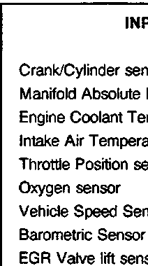
ECM Inputs and Outputs
PGM – Fi Fuel Injector Timing System
The fuel system utilises an Engine Control Module which controls both the the fuel injection and the ignition systems. The injection system is a sequential multi – point configuration, injecting fuel into the intake ports. Each injector opens at the precise time that the piston is on the intake stroke. The ECM contains settings for the basic injector opening durations at various engine speeds and manifold pressures. The basic injector opening duration, after being read from memory, is further modified by signals sent from other sensors to obtain the final opening duration.
Idle Air Control (IAC) Valve
When the engine is cold or the A/C compressor is on, or the Automatic Transmission is in gear, or the alternator is charging, the ECM controls the signal to the IAC valve to maintain the correct idle speed.
Ignition Timing Control
The ECM contains settings for basic ignition timing at various engine speeds and manifold pressures. Ignition timing is also adjusted for engine coolant temperature.
Other Control Functions
- Starting Control
- When the engine is started, the ECM provides a rich mixture by increasing injector duration.
- Fuel Pump Control
- When the ignition switch is initially turned on, the ECM supplies an earth to the main relay that supplies current to the fuel pump for two seconds, this pressurises the fuel system.
- When the engine is running, the ECM supplies an earth to the main relay that supplies current to the fuel pump.
- When the engine is not running and the ignition is ON, the ECM breaks the earth to the main relay which cuts the current supply to the fuel pump.
- Fuel Cut – off Control
- During deceleration with the throttle valve closed, supply to the fuel injectors is cut off to improve fuel economy at speeds over 1500 rpm.
- Fuel cut – off action also takes place when engine speed exceeds 6600 rpm regardless of the position of the throttle valve to protect the engine from over – revving.
Parts & tools for this job For Rover 600
- PARTEngine gasket setSearch: Rover 600 engine gasket set
- TOOLTorque wrenchSearch: 3/8 inch torque wrench
- TOOLFeeler gauge setSearch: feeler gauge set
Links open Amazon search results in a new tab. As an Amazon Associate I earn from qualifying purchases.