
Circuit diagram
- Make
- Rover
- Model
- 600 Rover 600 Repair Manual - Volumes 1 and 2 - 2nd Edition
- Section
- Information › Circuit diagram
Engine management system – PGM-FiCircuit diagram · page 1 of 2
CIRCUIT DIAGRAM
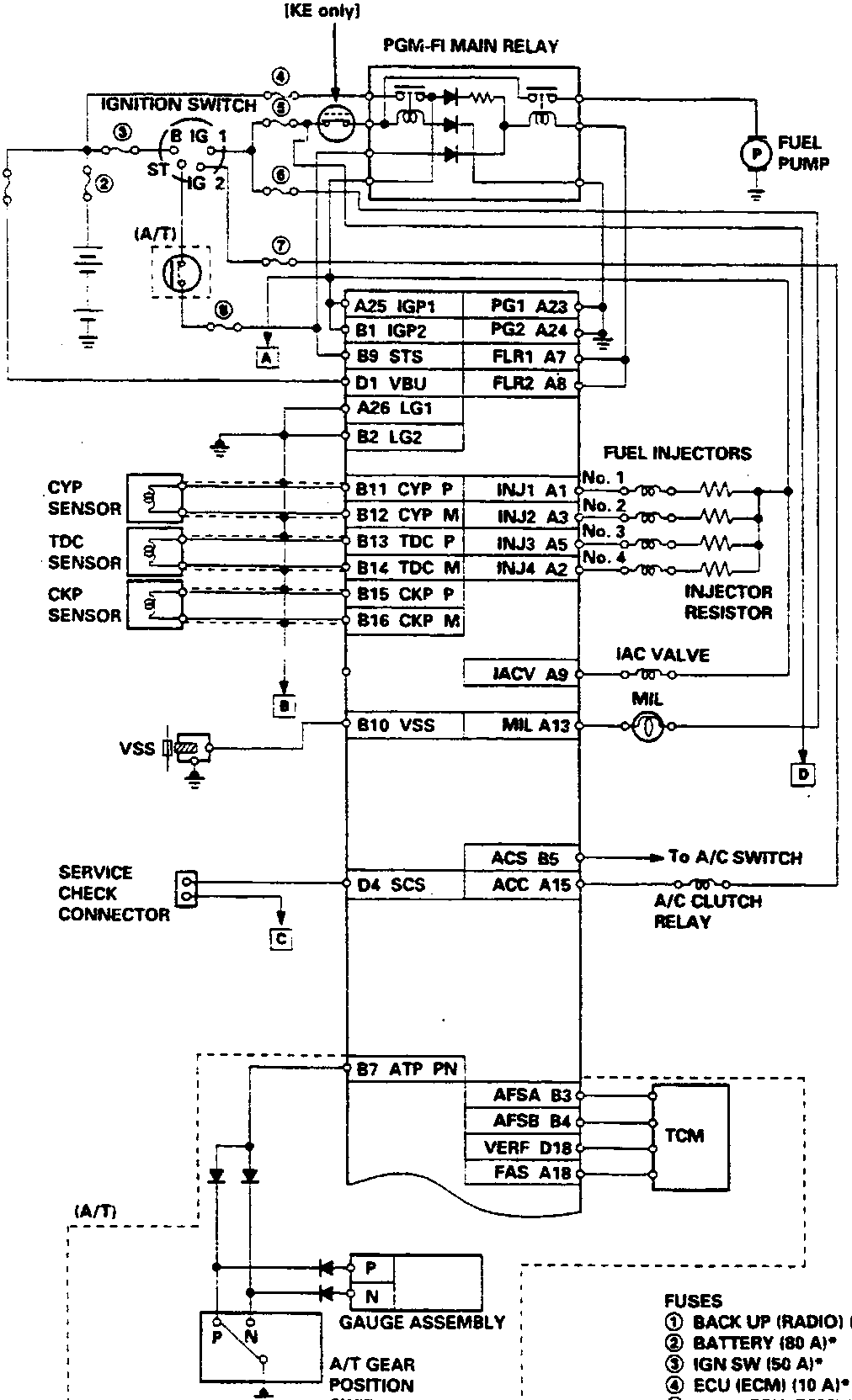
FUSES
- BACK UP (RADIO) (7.5 A)*
- BATTERY (80 A)*
- IGN SW (50 A)*
- ECU (ECM) (10 A)*
- No. 2 (ECU, ECM) (15 A)
- No. 8 (TURN SIGNALS) (10 A)
- No. 9 (A/C CLUTCH RELAY) (7.5 A)
- No. 12 (STARTER SIGNAL) (7.5 A)
*: In the under-hood fuse/relay box
Parts & tools for this job For Rover 600
- TOOLDigital multimeterSearch: automotive digital multimeter
- PARTAssorted fuse kitSearch: car fuse assortment kit
- TOOLWire crimper and connector kitSearch: wire crimper connector kit
Links open Amazon search results in a new tab. As an Amazon Associate I earn from qualifying purchases.