
Inertia switch (page 2 of 2)
- Make
- Rover
- Model
- 600 Rover 600 Repair Manual - Volumes 1 and 2 - 2nd Edition
- Section
- Information
Engine management system – PGM-FiInertia switch · page 2 of 2
The main relay is located under the right hand side of the fascia (L.H. side for LHD vehicles).
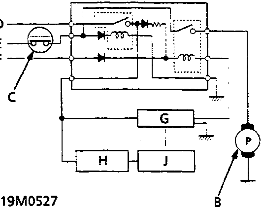
| A | PGM – Fi main relay | F | Starter signal |
| B | Fuel pump | G | ECM |
| C | Inertia switch [KE only] | H | Injector resistor |
| D | Battery voltage | J | Fuel injector |
| E | Ignition switch |
The PGM – Fi main relay contains two individual relays.
- One relay is energised whenever the ignition is ON and it supplies the battery voltage to the ECM, power to the fuel injectors, and power for the second relay.
- The second relay is energised for 2 seconds when the ignition is switched ON, and when the engine is running it supplies power to the fuel pump.
Parts & tools for this job For Rover 600
- TOOLOBD2 scannerSearch: OBD2 scanner
- TOOLDigital multimeterSearch: automotive digital multimeter
- TOOLBack-probe test leadsSearch: back probe test leads
Links open Amazon search results in a new tab. As an Amazon Associate I earn from qualifying purchases.