
Flow charts (page 2 of 8)
- Make
- Rover
- Model
- 600 Rover 600 Repair Manual - Volumes 1 and 2 - 2nd Edition
- Section
- Precautions
Supplementary restraint system (SRS)Flow charts · page 2 of 8
From page 3
- Reconnect the SRS main harness 4-P connector to the main wire harness.
- Disconnect the negative and positive battery cables, and wait 3 minutes.
- Remove the airbag assembly from the steering wheel.
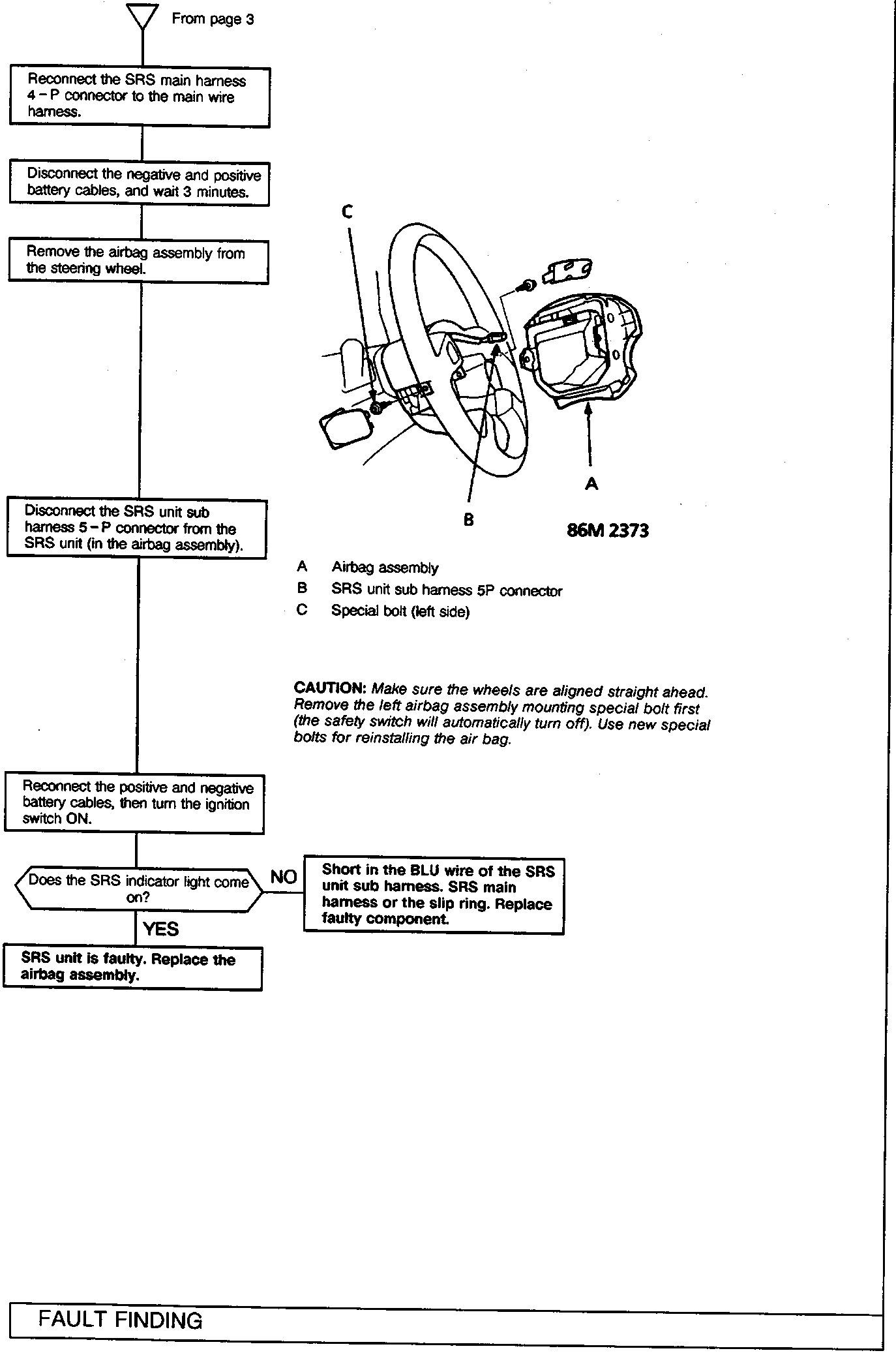
- Airbag assembly
- SRS unit sub harness 5P connector
- Special bolt (left side)
CAUTION: Make sure the wheels are aligned straight ahead. Remove the left airbag assembly mounting special bolt first (the safety switch will automatically turn off). Use new special bolts for reinstalling the air bag.
- Disconnect the SRS unit sub harness 5-P connector from the SRS unit (in the airbag assembly).
- Reconnect the positive and negative battery cables, then turn the ignition switch ON.
Does the SRS indicator light come on?
- YES
SRS unit is faulty. Replace the airbag assembly. - NO
Short in the BLU wire of the SRS unit sub harness. SRS main harness or the slip ring. Replace faulty component.
Parts & tools for this job For Rover 600
- TOOLOBD2 scanner with SRSSearch: OBD2 scanner ABS SRS
- TOOLTrim removal tool kitSearch: trim removal tool kit
Links open Amazon search results in a new tab. As an Amazon Associate I earn from qualifying purchases.