
Flow charts (page 8 of 8)
- Make
- Rover
- Model
- 600 Rover 600 Repair Manual - Volumes 1 and 2 - 2nd Edition
- Section
- Precautions
Supplementary restraint system (SRS)Flow charts · page 8 of 8
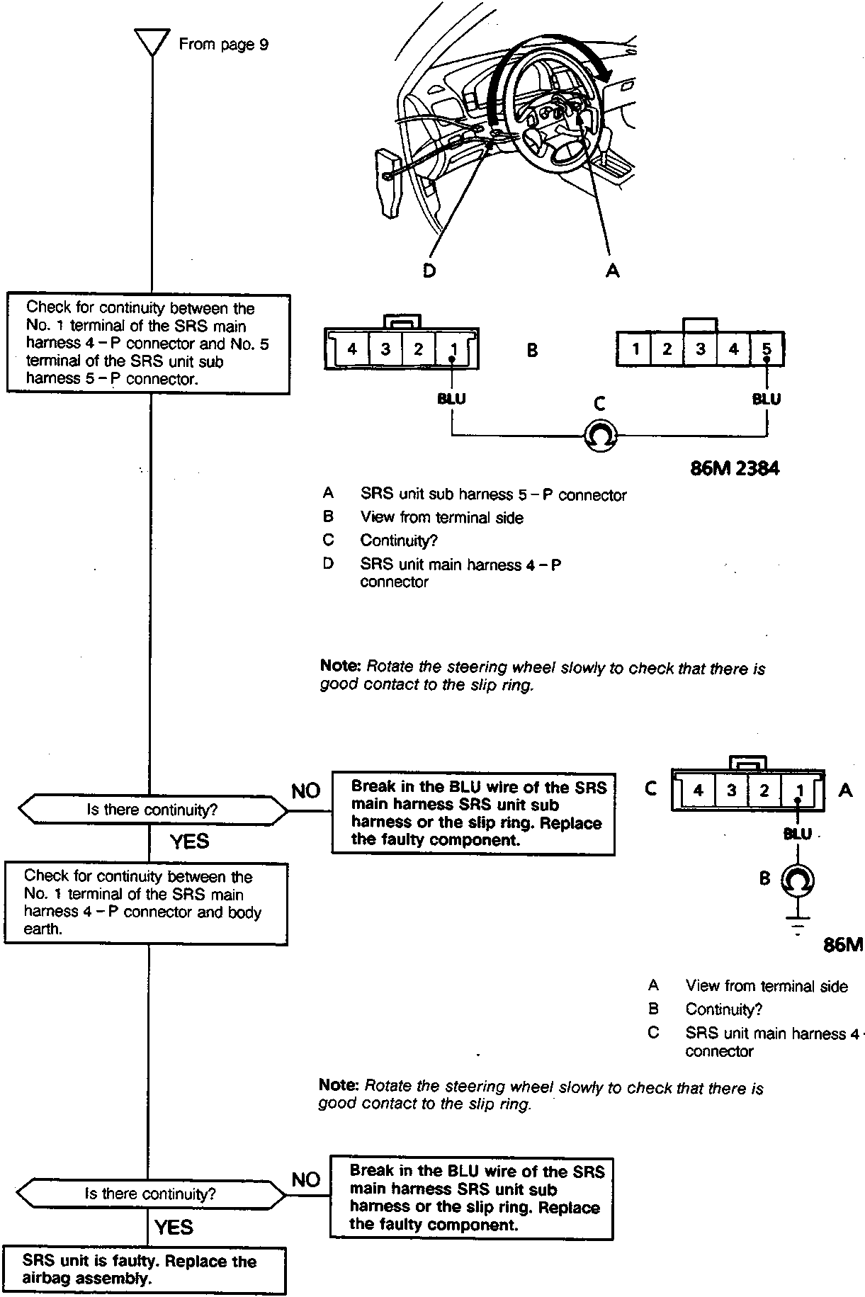
- From page 9
Check for continuity between the No. 1 terminal of the SRS main harness 4 – P connector and No. 5 terminal of the SRS unit sub harness 5 – P connector.
- SRS unit sub harness 5 – P connector
- View from terminal side
- Continuity?
- SRS unit main harness 4 – P connector
Note: Rotate the steering wheel slowly to check that there is good contact to the slip ring.
- Is there continuity? NO Break in the BLU wire of the SRS main harness SRS unit sub harness or the slip ring. Replace the faulty component.
- Is there continuity? YES Check for continuity between the No. 1 terminal of the SRS main harness 4 – P connector and body earth.
- View from terminal side
- Continuity?
- SRS unit main harness 4 – P connector
Note: Rotate the steering wheel slowly to check that there is good contact to the slip ring.
- Is there continuity? NO Break in the BLU wire of the SRS main harness SRS unit sub harness or the slip ring. Replace the faulty component.
- Is there continuity? YES SRS unit is faulty. Replace the airbag assembly.
Parts & tools for this job For Rover 600
- TOOLOBD2 scanner with SRSSearch: OBD2 scanner ABS SRS
- TOOLTrim removal tool kitSearch: trim removal tool kit
Links open Amazon search results in a new tab. As an Amazon Associate I earn from qualifying purchases.