
Schematic layout of air conditioning system
- Make
- Rover
- Model
- Coupé, Cabriolet & Tourer 200/400 Coupé, Cabriolet & Tourer Workshop Manual Supplement
- Section
- Description and operation › Schematic layout of air conditioning system
Air conditioningSchematic layout of air conditioning system
SCHEMATIC LAYOUT OF AIR CONDITIONING SYSTEM
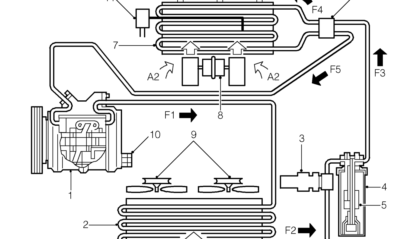
- Compressor
- Condenser
- Trinary pressure switch
- Receiver/dryer
- Drying agent - receiver/dryer
- Thermostatic expansion valve
- Evaporator
- Heater blower motor
- Condenser cooling fans
- Compressor high pressure relief valve
- Thermostat and sensing tube
A1. Ambient air flow through condenser A2. Ambient air flow through fan and evaporator A3. Cooled air flow to vehicle interior F1. High pressure, high temperature refrigerant vapour F2. High pressure, slightly subcooled refrigerant liquid F3. High pressure, slightly subcooled refrigerant liquid with moisture, vapour bubbles and foreign matter removed F4. Low pressure, low temperature mixed liquid and vapour F5. Low pressure, slightly superheated refrigerant vapour
Parts & tools for this job For Rover Coupé, Cabriolet & Tourer
- TOOLA/C manifold gauge setSearch: AC manifold gauge set
- TOOLUV leak detection kitSearch: AC UV leak detection kit
- PARTCabin filterSearch: Rover Coupé, Cabriolet & Tourer cabin filter
Links open Amazon search results in a new tab. As an Amazon Associate I earn from qualifying purchases.