
Refit
- Make
- Rover
- Model
- Coupé, Cabriolet & Tourer 200/400 Coupé, Cabriolet & Tourer Workshop Manual
- Section
- Repairs › Refit
Engine 1.6 D.O.H.C.Refit
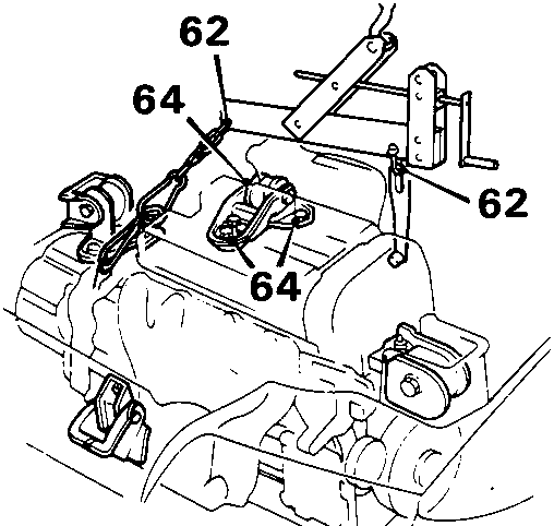
- Attach engine lift tilt adapter to lifting chains and lifting bracket, and support weight of engine.
CAUTION: Do not slacken front mounting through bolt.
- Remove 3 bolts, rear mounting bracket to gearbox bracket.
- Slacken rear mounting through bolt, raise mounting bracket clear of gearbox.
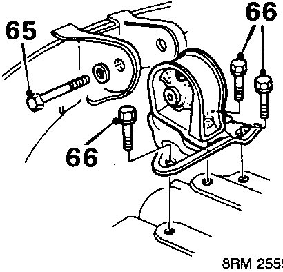
- Remove through bolt R.H. mounting to body.
- Remove 3 bolts, R.H. mounting plate to gearbox and remove mounting.
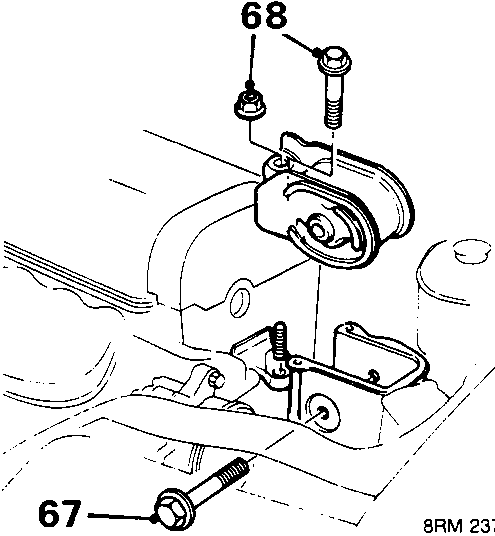
- Remove through bolt, L.H. engine mounting to body.
- Remove 1 bolt and nut, L.H. mounting bracket to cylinder block and remove mounting.
- Raise engine and gearbox and manoeuvre clear of engine compartment.
CAUTION: Ensure lifting chains do not contact camshaft cover.
Refit
- Attach engine lift tilt adaptor tool 18G 1598 to engine and gearbox brackets, lower engine and gearbox into position ensuring that front mounting bracket is aligned to gearbox.
CAUTION: Ensure lifting chains do not contact camshaft cover.
- Fit L.H. mounting, tighten bolts to 55 Nm. Fit through bolt and washer, do not tighten.
- Align front mounting bracket to gearbox; tighten bolts to 55 Nm. Fit NEW through bolt and washer, do not tighten.
- Fit R.H. mounting plate, tighten bolts to 55 Nm. Fit through bolt and washer, do not tighten.
- Align rear mounting bracket to gearbox; tighten bolts to 55 Nm. Fit NEW through bolt, do not tighten.
- Finally tighten mounting through bolts as follows:
Rear mounting to 60 Nm.
Front mounting to 60 Nm.
R.H. mounting to 60 Nm.
L.H. mounting to 55 Nm. - Disconnect lifting chains from brackets.
- Remove engine lifting bracket and spacer.
- Connect L.H. drive to intermediate shaft see AUTOMATIC GEARBOX 1.6 – Repairs – Differential oil seal – L.H.
- Connect R.H. drive shaft to differential see AUTOMATIC GEARBOX 1.6 – Repairs – Differential oil seal – R.H.
Parts & tools for this job For Rover Coupé, Cabriolet & Tourer
- PARTEngine gasket setSearch: Rover Coupé, Cabriolet & Tourer engine gasket set
- TOOLTorque wrenchSearch: 3/8 inch torque wrench
- TOOLFeeler gauge setSearch: feeler gauge set
Links open Amazon search results in a new tab. As an Amazon Associate I earn from qualifying purchases.