
Link mount on engine - r r
- Make
- Alfa Romeo
- Model
- 147 Factory Service Manual
- Year
- 2000–2004
- Section
- Power unit supports › Link mount on engine - r r
Link mount on engine - r r
Removing
Position the vehicle on the ramp.
Ensure that the ignition key is in the OFF postition, then disconnect the battery negative terminal.
| Name | Connector | |
|---|---|---|
| Battery | A1B |
Proceed with the removal - 4450B10 Front WHEEL (one) - R.R. (Right side).
Proceed with the removal - 7055B64 Engine compartment DUST shield in front wheel arch (one), left or right - R.R. (Right side).
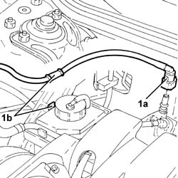
1. Disconnect the rapid attachment (1a) for the fuel vapour recovery pipe and release it from the fastening (1b) on the power assisted steering fluid reservoir.
Plug the fuel vapour recovery system pipes.
Proceed with the removal - 1016A40 ignition coil cover on cylinder head- r+r.
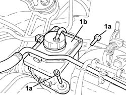
1. Undo the bolts (1a) and remove the power assisted steering fluid reservoir (1b).
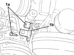
1. Undo the bolts (1a) and release the power assisted steering fluid mounting bracket (1b) from the support on the engine for the reaction rod and the various engine components.
Proceed with the removal - 1008C10 power unit upper reaction link r r.
Proceed with the removal - 5510C14 ignition coil/s - r+r.
Proceed with the removal - 1016A20 single cam cover - r + r and replace gasket.
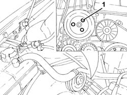
1. Loosen the bolts fixing the power assisted steering pump pulley.
Proceed with the removal - 1092G10 single engine belt r r.
Proceed with the removal - 1092A10 Crankshaft services PULLEY - R.R..
Proceed with the removal - 1092G20 engine component single belt fixed tensioner - one - r + r.
Proceed with the removal - 1032D12 timing system protective cover(s) - r + r.
Proceed with the removal - 1032B10 toothed timing belt - r + r for timing adjustment or replacement.
Proceed with the removal - 1032C18 mobile timing system tensioner - r + r for 24 valve engines.
Proceed with the removal - 1032C30 fixed timing system tensioner - r + r with timing belt removed.
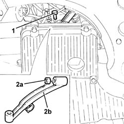
1. Undo the bolt fixing the alternator rear mounting to the cylinder block/crankcase.
2. Undo the upper bolt (2a) fixing the alternator and remove the alternator rear mounting bracket (2b).
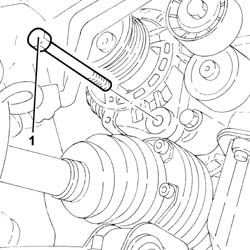
1. Undo the lower alternator fixing bolt.
Move the alternator away from the support on the engine for the reaction rod and the various engine components and secure it suitably.
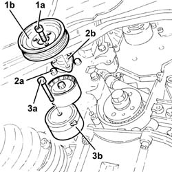
1. Completely undo the bolts (1a) loosened previously and remove the power assisted steering pump pulley (1b).
2. Undo the bolts (2a) and move the power assisted steering pump (2b) away from the support.
3. Undo the bolt (3a) and remove the engine components single drive belt moving tensioner (3b).
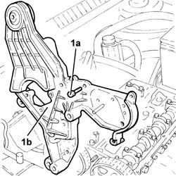
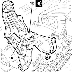
1. Undo the bolts (1a) and remove the support on the enigne for the reaction rod and the various engine components (1b).
Refitting
1. Place the support on the engine for the reaction rod and the various engine components (1a) and fix it by tightening the bolts (1b) to the recommended torque.
| Fastening | Component | Ø | Value (daNm) | |
|---|---|---|---|---|
| 1b | Bolt | ENGINE LINK AND VARIOUS COMPT.MOUNTS | M8 | 2.3 ÷ 2.8 |
| Fastening | Component | Ø | Value (daNm) | |
|---|---|---|---|---|
| 1b | Bolt | ENGINE LINK AND VARIOUS COMPT.MOUNTS | M8 | 4.5 ÷ 5.5 |
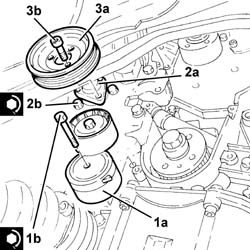
1. Place the engine components single drive belt moving tensioner (1a) back in its housing and fix it tightening the bolts (1b) to the recommended torque.
| Fastening | Component | Ø | Value (daNm) | |
|---|---|---|---|---|
| 1b | Bolt | SINGLE SERVICES MOBILE BELT TENSIONER | M8 | 2.3 ÷ 2.8 |
2. Place the power assisted steering pump (2a), complete with pipes, back in its housing and secure it by tightening the bolts (2b) to the recommended torque.
| Fastening | Component | Ø | Value (daNm) | |
|---|---|---|---|---|
| 2b | Bolt | POWER STEERING PUMP | M8 | (Support side) 2.3 ÷ 2.8 |
3. Place the power assisted steering pump drive pulley (3a) back in its housing and secure it using the bolts (3b) without tightening them.
Place the alternator back in its housing and secure it using the lower bolt without tightening it.
Place the alternator rear mounting bracket back in its housing.
Tighten the bolts fixing the alternator to the recommended torque.
| Fastening | Component | Ø | Value (daNm) | |
|---|---|---|---|---|
| Bolt | ALTERNATOR ASSEMBLY | M10 | 4.5 ÷ 5.5 |
| Fastening | Component | Ø | Value (daNm) | |
|---|---|---|---|---|
| Bolt | ALTERNATOR ASSEMBLY | M12 | 6.3 ÷ 7.7 |
Tighten the bolts fixing the alternator rear mounting to the cylinder block/crankcase.
Proceed with the refitting - 1032C30 fixed timing system tensioner - r + r with timing belt removed.
Proceed with the refitting - 1032C18 mobile timing system tensioner - r + r for 24 valve engines.
Proceed with the refitting - 1032B10 toothed timing belt - r + r for timing adjustment or replacement.
Proceed with the refitting - 1032D12 timing system protective cover(s) - r + r.
Proceed with the refitting - 1092G20 engine component single belt fixed tensioner - one - r + r.
Proceed with the refitting - 1092A10 Crankshaft services PULLEY - R.R..
Proceed with the refitting - 1092G10 single engine belt r r.
Tighten the power steering pump pulley bolts to the specified torque.
| Fastening | Component | Ø | Value (daNm) | |
|---|---|---|---|---|
| Bolt | POWER STEERING PUMP DRIVE PULLEY | M8 | (Power assisted steering pump side) 2.3÷2.8 |
Proceed with the refitting - 1016A20 single cam cover - r + r and replace gasket.
Proceed with the refitting - 5510C14 ignition coil/s - r+r.
Proceed with the refitting - 1008C10 power unit upper reaction link r r.
Place the power assisted steering fluid reservoir mounting bracket back in its housing and secure it using the bolts.
Refit in its seating the power steering fluid reservoir and secure it with its bolts.
Proceed with the refitting - 1016A40 ignition coil cover on cylinder head- r+r.
Connect the rapid attachment for the fuel vapour recovery pipe and secure it to the band on the power assisted steering fluid reservoir.
Proceed with the refitting - 7055B64 Engine compartment DUST shield in front wheel arch (one), left or right - R.R. (Right side).
Proceed with the refitting - 4450B10 Front WHEEL (one) - R.R. (Right side).
Connect the battery terminal (-).
Remove the car from the ramp.
Parts & tools for this job For 2000 Alfa Romeo 147
- PARTEngine gasket setSearch: Alfa Romeo 147 2000 engine gasket set
- TOOLTorque wrenchSearch: 3/8 inch torque wrench
- TOOLFeeler gauge setSearch: feeler gauge set
Links open Amazon search results in a new tab. As an Amazon Associate I earn from qualifying purchases.