
Cylinder heads (page 6 of 12)
- Make
- Alfa Romeo
- Model
- GTV / Spider GTV and Spider (916) Factory Service Manual
- Year
- 1995–2000
- Section
- Operations in vehicle (24V)
Variants – 3.0 V6 24VCylinder heads · page 6 of 12
- Disconnect the fuel delivery pipe from the distributor manifold.
- Disconnect the excess fuel return pipe from the pressure regulator.
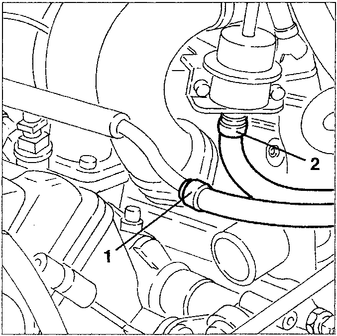
- fuel delivery pipe
- excess fuel return pipe
- Disconnect the electrical connection from the constant idle speed device.
- Disconnect the fuel vapour recovery pipe from the intake box.
- Disconnect the servobrake vacuum takeoff pipe from the intake box.
- Disconnect the oil vapour recovery pipe from the separator.
- Disconnect the condensed oil recovery pipe from the separator.
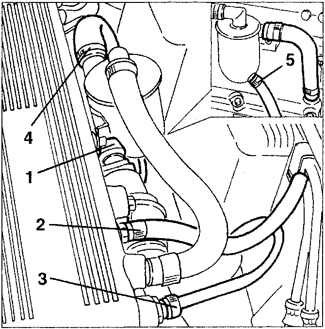
- fuel vapour recovery pipe
- servobrake vacuum takeoff pipe
- oil vapour recovery pipe
- condensed oil recovery pipe
- separator
- Disconnect the climate control system heater coolant delivery sleeve from the fitting on the cylinder head.
- Disconnect the climate control system heater coolant return sleeve from the thermostatic cup.
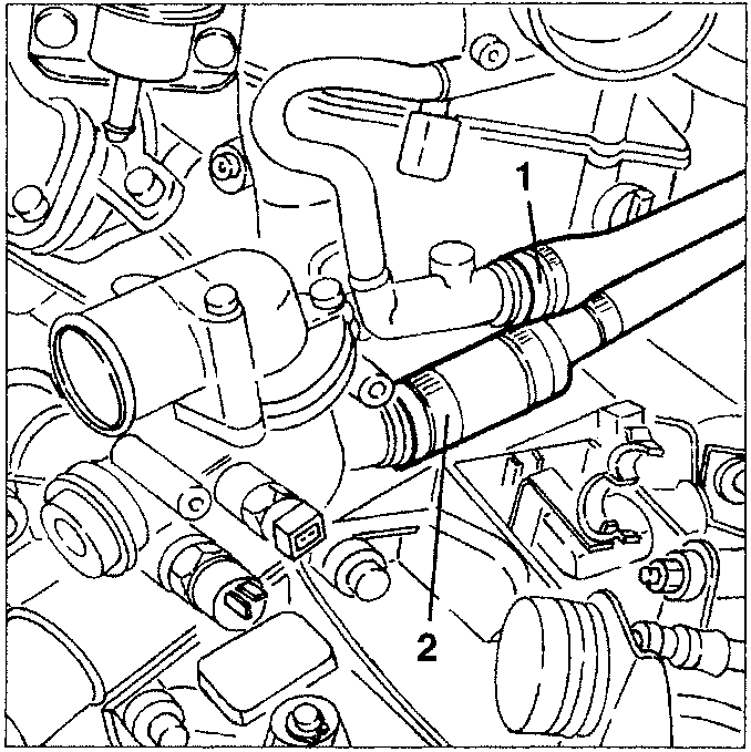
- climate control system heater coolant delivery sleeve
- climate control system heater coolant return sleeve
- Disconnect the vacuum pipe leading from the modulating solenoid valve from the E.G.R. valve.
- Slacken the two fastening screws and remove the E.G.R. valve complete with exhaust gas takeoff pipe.
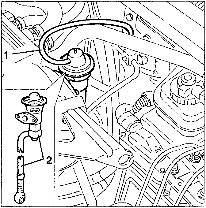
- vacuum pipe
- E.G.R. valve
Parts & tools for this job For 1995 Alfa Romeo GTV / Spider
- PARTEngine gasket setSearch: Alfa Romeo GTV / Spider 1995 engine gasket set
- TOOLTorque wrenchSearch: 3/8 inch torque wrench
- TOOLFeeler gauge setSearch: feeler gauge set
Links open Amazon search results in a new tab. As an Amazon Associate I earn from qualifying purchases.