
Workshop Manuals Factory service & repair Fiat
01 00 Introduction and technical data02 10 Engine03 18 Clutch04 21 Gearbox and differential05 33 Braking system06 41 Steering07 44 Suspension and wheels08 50 Auxiliary units09 55 Electrical system10 70 Bodywork
Fiat Bravo/Brava (182) Factory Service Manual (1995-2001)02 · 10 Engine
02 · Engine

Checking resistance

Make
Fiat
Model
Bravo /Brava (182) Factory Service Manual
Year
1995–2001
Section
Fuel system (1581 16v) › Checking resistance
10 EngineChecking resistance
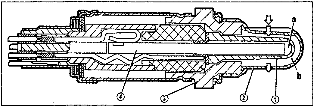
Cross-section diagram of a lambda probe showing internal components including ceramic case, protective pipe, metal case, and electrical resistant, with callouts for electrodes in contact with outside air and exhaust gas.
a. Electrode (+) in contact with outside air b. Electrode (-) in contact with exhaust gas 1. Ceramic case 2. Protective pipe 3. Metal case 4. Electrical resistant When the probe supplies a low voltage level (less than 200 mV) the ECU recognises that the mixture is lean (lambda » 1) and takes steps to increase the amount of fuel injected. When the probe supplies a high voltage level (greater than 800 mV) the control unit recognises that the mixture is rich (lambda « 1) and decreases the quantity of fuel injected. The lambda probe therefore alters injection times to ensure that the engine operates with a lambda factor continually fluctuating between 0.980 and 1.020. Below 300 °C the ceramic material is not active and the probe does not send usable signals. A special circuit in the control unit blocks loop mixture regulation while the probe is warming up. To ensure service temperature is reached quickly, the probe is equipped with electrical resistance (4) supplied by the battery

The probe may be swiftly put out of service by even slight traces of lead in the fuel. Operation should be checked at 45,000 and 90,000 km in accordance with the programmed maintenance plan.
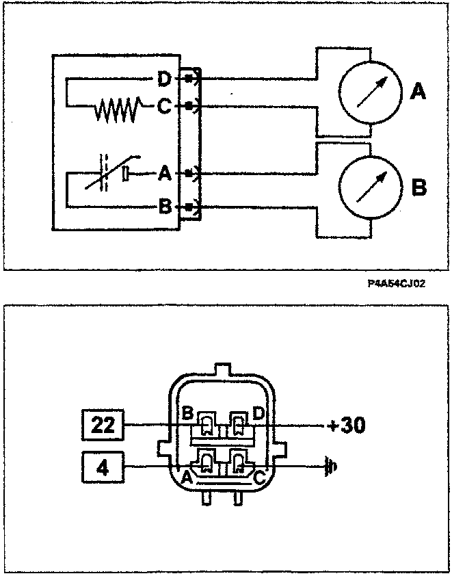
Schematic wiring diagram showing connections for heater resistance (A) and probe resistance (B) measured with an ohmmeter across terminals D, C, A, B.

Checking resistance

The heater and probe resistance may be measured by disconnecting the connector and connecting an ohmmeter as indicated in the figure. Heater resistance (A) = 4.3 - 4.7 ohm Probe resistance (B) = 5000 ohm (max)

Recovery

Lambda data are ignored (open loop).

Wiring connector

The numbers in boxes indicate the corresponding control unit pins.

Parts & tools for this job For 1995 Fiat Bravo

Links open Amazon search results in a new tab. As an Amazon Associate I earn from qualifying purchases.