
Fuel evaporation control circuit diagram
- Make
- Fiat
- Model
- Bravo /Brava (182) Factory Service Manual
- Year
- 1995–2001
- Section
- Fuel system (1581 16v) › Fuel evaporation control circuit diagram
10 EngineFuel evaporation control circuit diagram
FUEL EVAPORATION CONTROL CIRCUIT DIAGRAM
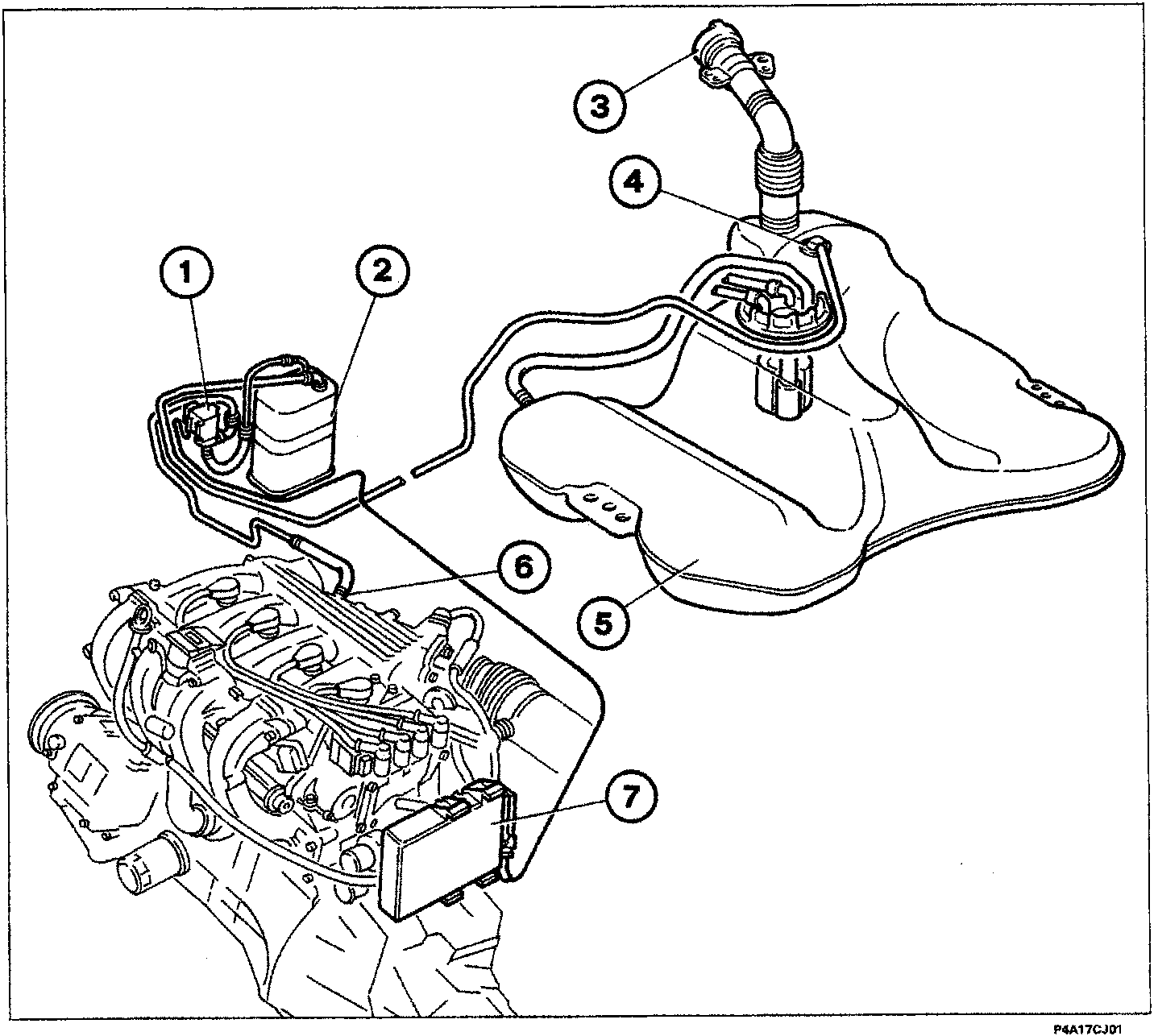
The fuel evaporation system prevents fuel vapour, mainly comprising lighter hydrocarbon fractions formed in the tank, to escape into the atmosphere.
- Fuel vapour cut-off valve
- Active carbon trap filter
- Safety and ventilation valve
- Multifunction valve
- Reservoir
- Fuel vapour intake fitting in intake manifold
- Injection-ignition ECU
Parts & tools for this job For 1995 Fiat Bravo
- TOOLDigital multimeterSearch: automotive digital multimeter
- PARTAssorted fuse kitSearch: car fuse assortment kit
- TOOLWire crimper and connector kitSearch: wire crimper connector kit
Links open Amazon search results in a new tab. As an Amazon Associate I earn from qualifying purchases.