
Signal management
- Make
- Fiat
- Model
- Bravo /Brava (182) Factory Service Manual
- Year
- 1995–2001
- Section
- Fuel system (1581 16v) › Signal management
The management strategies must not only control the moment of ignition and intake air temperature/pressure at various engine speeds in order to allow the engine to work properly as environmental parameters change, but also control and manage injection in order to maintain an optimal stoichiometric ratio (air/fuel) at all times.
System management strategies are essentially as follows:
- -signal management;
- -injection management;
- -Fiat CODE ignition lock function management);
- -ignition management;
- -engine idle control;
- -fuel vapour recirculation management;
- -test management
- -heating/ventilation system management
SIGNAL MANAGEMENT
Upon starting, the ECU identifies injection and ignition timing, because these parameters are essential to ensure subsequent successful implementation of all strategies.
Timing is identified by interpreting a series of signals from an rpm sensor located on the crankshaft pulley and a timing sensor located on the camshaft pulley, intake side.
NOTE The term "signal framework" denotes the set of signals produced by a sensor on the crankshaft and a sensor on the camshaft. Because these are located in specific reciprocal positions, they provide the ECU with a synchronised sequence of signals that the ECU is able to identify.
The signal framework is produced as follows:
- - phonic wheel on the crankshaft pulley, equipped with (60-2) 58 teeth and an angular gap of 18° (equivalent to two missing teeth) for TDC recognition.
- - wheel on camshaft pulley, intake side, comprises two long slots and one short slot, with width and arrangement designed to provide the signal indicated in the figure.
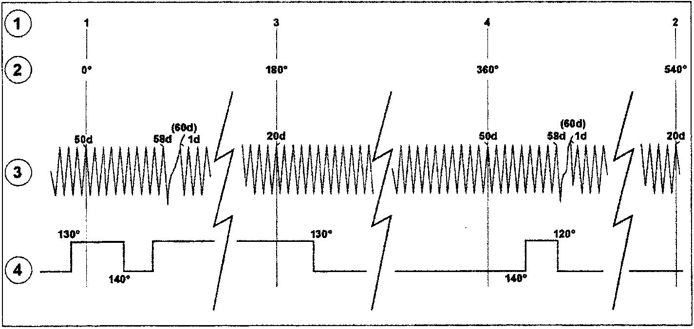
- Cylinder TDC
- Crankshaft angles
- Crankshaft phonic wheel signal (rpm sensor)
- Camshaft wheel signal (engine timing sensor)
NOTE Numbers allocated to signals indicate crankshaft angles ahead of subsequent TDC.
Parts & tools for this job For 1995 Fiat Bravo
- PARTFuel filterSearch: Fiat Bravo 1995 fuel filter
- TOOLFuel pressure test kitSearch: fuel pressure test kit
- TOOLFuel line disconnect toolSearch: fuel line disconnect tool
Links open Amazon search results in a new tab. As an Amazon Associate I earn from qualifying purchases.