
Ignition operating diagram
- Make
- Fiat
- Model
- Bravo /Brava (182) Factory Service Manual
- Year
- 1995–2001
- Section
- Fuel system (1581 16v) › Ignition operating diagram
The rising side of signal (graph B in figure on previous page) therefore represents a moment within which alternative primary winding conduction could take place. This point can be established only by the control unit power module. The conduction time the H.T. coil needs in order to store sufficient energy is also defined by DWELL management strategies. This depends on the time taken by the current to reach about 6A in the coil primary winding and also on the calculation algorithm run by the microprocessor which uses factors saved in a special memory, obviously based on engine rpm
With reference to the figure on the previous page, the falling side of the signal, (B) conduction end point (or current drop to zero), is a categorical order to cut-off the current flowing in the primary winding and represents the ignition advance point (a) processed by the computer (advance - (a) - varies according to rpm).
The control unit (ECU) then controls spark advance in the different cylinders in relation to top dead centre and conduction time necessary for the coil to store energy by controlling the two power stages (corresponding to ECU pins 55 and 37). These in turn permit current to flow through primary windings of coils (6) for long enough to ensure the specified 6A current rating.
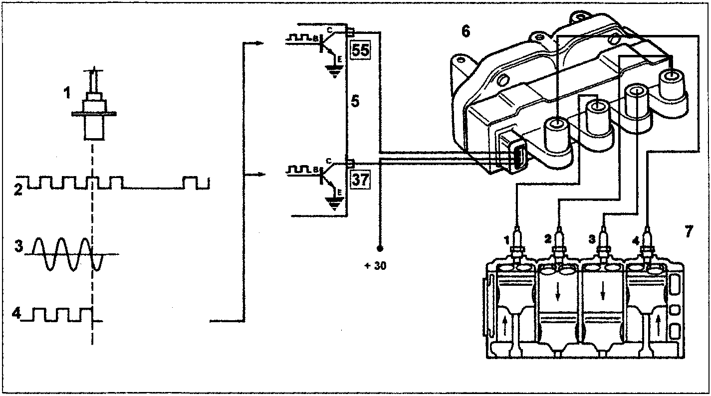
Ignition operating diagram
- RPM and TDC sensor.
- Phonic wheel.
- Signal pattern taken from phonic wheel (60-2) teeth.
TDCs correspond to teeth 20 and 50. - Succession of rectangular square wave signals of constant amplitude
- Ignition power module (inside control unit).
- Ignition coils.
- Spark plugs
NOTE The numbers in boxes indicate the corresponding control unit pins
At the moment when the ECU de-activates one of the two power stages, current flow is cut off. This generates a voltage by induction (up to 30kV without loads) in the secondary winding.
Parts & tools for this job For 1995 Fiat Bravo
- PARTFuel filterSearch: Fiat Bravo 1995 fuel filter
- TOOLFuel pressure test kitSearch: fuel pressure test kit
- TOOLFuel line disconnect toolSearch: fuel line disconnect tool
Links open Amazon search results in a new tab. As an Amazon Associate I earn from qualifying purchases.