
Heating/ventilation system management
- Make
- Fiat
- Model
- Bravo /Brava (182) Factory Service Manual
- Year
- 1995–2001
- Section
- Fuel system (1581 16v) › Heating/ventilation system management
‹ Prev Engine idle controlNext › Diagram showing input/output between injection-ignition system ECU and sensors/actuators
10 EngineHeating/ventilation system management
HEATING/VENTILATION SYSTEM MANAGEMENT
Rpm decreases when the air conditioner is turned on because the system compressor takes up power.
This involves a drop in rpm, which is particularly evident during idling.
To overcome this drawback, when the ECU is informed of air conditioner activation (pin 10) ahead of compressor activation (pin 26), it increases the speed by adjusting the air flow by means of the step motor.
When a power requirement is identified (throttle position higher than a given threshold) the ECU inhibits air conditioner operation for a memorized time interval.
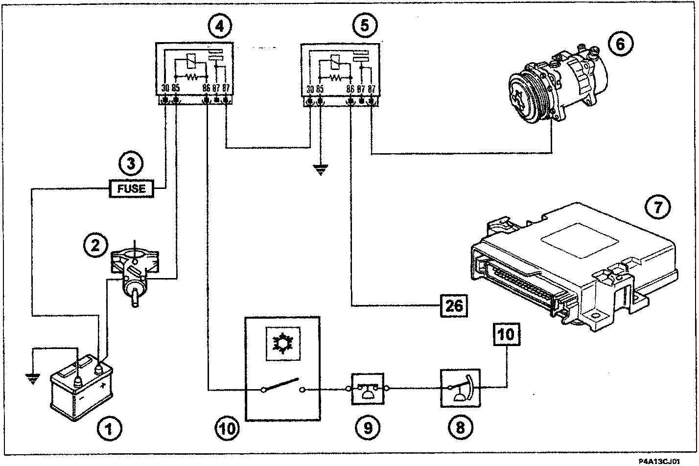
- Battery
- Ignition switch
- Fuse
- Air conditioning system enablement relay
- Compressor electromagnetic coupling supply relay
- Compressor
- Electronic injection-ignition control unit
- Three stage pressure switch
- Defrosting sensor
- Air conditioner activation switch
‹ Prev Engine idle controlNext › Diagram showing input/output between injection-ignition system ECU and sensors/actuators
Parts & tools for this job For 1995 Fiat Bravo
- TOOLA/C manifold gauge setSearch: AC manifold gauge set
- TOOLUV leak detection kitSearch: AC UV leak detection kit
- PARTCabin filterSearch: Fiat Bravo 1995 cabin filter
Links open Amazon search results in a new tab. As an Amazon Associate I earn from qualifying purchases.