
Wiring connector
- Make
- Fiat
- Model
- Bravo /Brava (182) Factory Service Manual
- Year
- 1995–2001
- Section
- Fuel system (1581 16v) › Wiring connector
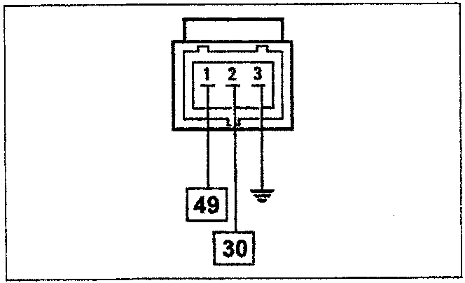
Wiring connector
The sensor is connected to the ECU (pin 30 and 49) by means of twisted wires covered by a shielded, interference-proof sheath connected to earth.
NOTE The numbers in boxes indicate the corresponding control unit pins.
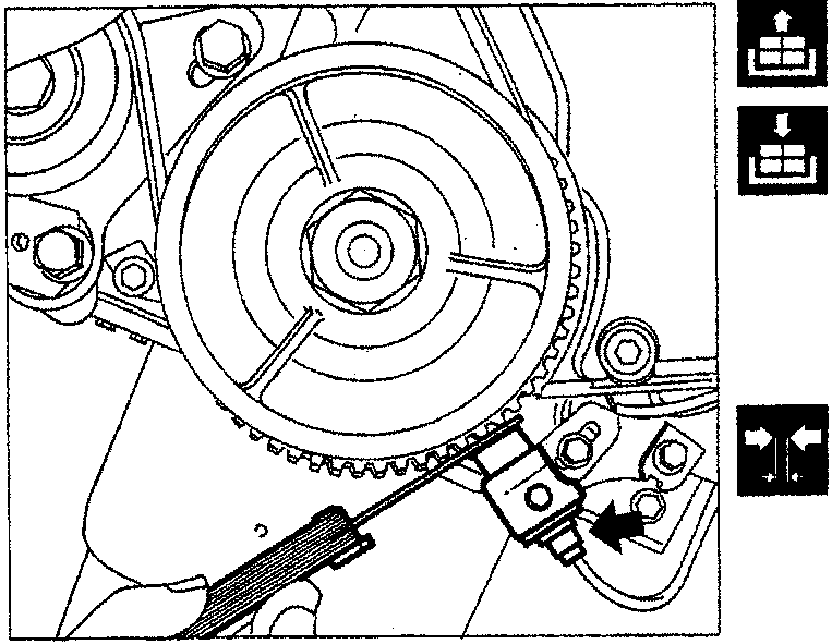
Removing-refitting
Disconnect electrical connection.
Unscrew the screw indicated and remove the sensor.
Checking gap
Check gap between sensor and phonic wheel teeth.
Gap: 0.5 - 1.5 mm
NOTE Whenever repairs to the rpm and TDC sensor mount are necessary (e.g. gap not as specified, sensor not aligned etc.), the sensor must be positioned and aligned with the mount as described in the engine service manual (publication no. 504.589/20).
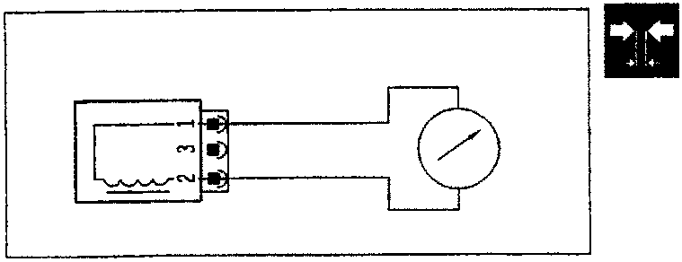
Checking resistance
Sensor resistance may be measured by disconnecting the connector and connecting an ohmmeter to the sensor terminals.
Resistance 575 - 750 ohm at 20 °C
Parts & tools for this job For 1995 Fiat Bravo
- TOOLDigital multimeterSearch: automotive digital multimeter
- PARTAssorted fuse kitSearch: car fuse assortment kit
- TOOLWire crimper and connector kitSearch: wire crimper connector kit
Links open Amazon search results in a new tab. As an Amazon Associate I earn from qualifying purchases.