
Motor strategy
- Make
- Fiat
- Model
- Bravo /Brava (182) Factory Service Manual
- Year
- 1995–2001
- Section
- Fuel system (1581 16v) › Motor strategy
10 EngineMotor strategy
Motor strategy
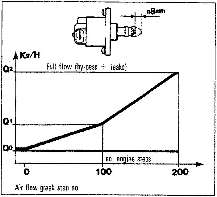
The number of working steps is dependent upon engine conditions: - Start-up stage When the key is inserted, the ECU controls step motor position according to engine coolant temperature and battery voltage. - Warming-up stage Rpm levels are corrected according to engine coolan temperature. - With engine warm: Idle control is dependent on a signal from the rpm sensor. When external users are activated, the ECU governs sustained idle. - Over-run: The ECU recognises over-run status from the throttle potentiometer position. It controls step motor position by means of the idle flow law (DASH-POT laws). In other words, it slows the return of pluger (3) to its seat so that a quantity of air by-passing hole (2) reaches the engine and reduces levels of pollutants in the exhaust gas.Recovery
Actuator operation disenabled and self-adaption of idling fuel mixture level blocked.Removing-refitting engine idle control actuator (step motor)
- disconnect battery negative terminal; - unscrew both retaining screws and withdraw the actuator; - check condition of thoroid seal and remove any impurities from the case seat; - refit the actuator, checking that the plunger fits easily without forcing. To do this, fit the actuator and replace screws but do not tighten. Operate the step motor using a Fiat-Lancia/Tester until it has moved through its entire travel. Tighten screws only after checking plunger is correctly aligned in its seat and electrical connector is positioned correctly.NOTE It is advisable to leave the battery negative terminal disconnected for about 20 minutes. Provided the above procedure is carried out as described, the ECU will position the idle speed actuator correctly the first time the engine is started up.
Fit new step motor retaining screws whenever they are loosened or removed because the threads are covered with a light layer of loctye, which guarantees a seal only once.
Tightening torque of step motor screws 0.36 - 0.44 da Nm.
Parts & tools for this job For 1995 Fiat Bravo
- PARTFuel filterSearch: Fiat Bravo 1995 fuel filter
- TOOLFuel pressure test kitSearch: fuel pressure test kit
- TOOLFuel line disconnect toolSearch: fuel line disconnect tool
Links open Amazon search results in a new tab. As an Amazon Associate I earn from qualifying purchases.