
Timing sensor (sfa 200)
- Make
- Fiat
- Model
- Bravo /Brava (182) Factory Service Manual
- Year
- 1995–2001
- Section
- Fuel system (1581 16v) › Timing sensor (sfa 200)
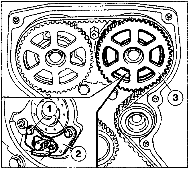
NOTE Sensor angular position may not be adjusted in any way.
TIMING SENSOR (SFA 200)
The I.A.W.-1AF.13 system adopts a phased, sequential injection system. In other words, fuel is injected into each cylinder in sequence during the intake phase.
To achieve this, the ECU uses a timing signal together with the rpm and TDC signal to determine the point of injection.
This signal is generated by a Hall sensor fitted on the exhaust camshaft pulley.
Principle of operation
A semi-conducting layer with current flowing through it is placed in a normal magnetic field (force lines at right angles to current direction). A potential difference known as a HALL voltage is set up at its terminals.
If current intensity remains constant, the voltage generated depends solely on the intensity of the magnetic field; magnetic field intensity need therefore only vary periodically to set up a modulated electrical signal with frequency proportional to the speed with which the magnetic field changes.
To achieve this change, the sensor is crossed by a metal ring (internal part of pulley) with an opening. The moving metal part of the ring covers the sensor and blocks the magnetic field to produce a low output signal. The sensor generates a high signal when aligned with the opening, i.e. with magnetic field present.
The alternation of signals is therefore dependent on the succession of openings (see chapter on "signal management").
Removing-refitting
To gain access to the timing sensor, remove the intake side camshaft pulley (3) (refer to engine service manual, publication no. 504.589/20).
Disconnect electrical connection of sensor.
Unscrew both screws (1) and remove timing sensor (2) with retaining plate.
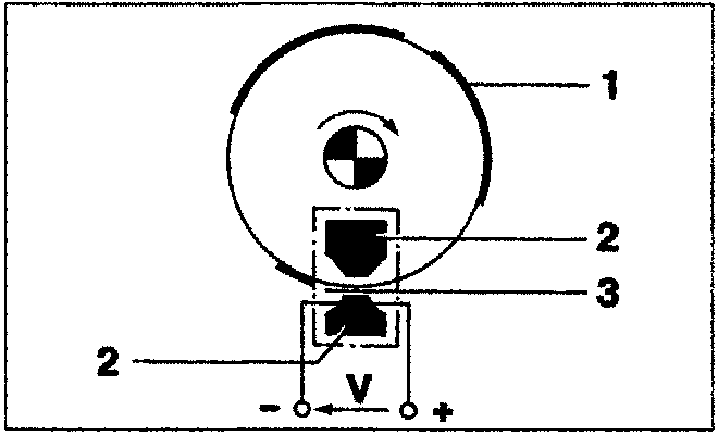
- Deflector
- Magnetic material
- Gap
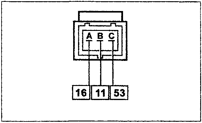
Wiring connector
The numbers in boxes indicate the corresponding control unit pins
Parts & tools for this job For 1995 Fiat Bravo
- TOOLOBD2 scannerSearch: OBD2 scanner
- TOOLDigital multimeterSearch: automotive digital multimeter
- TOOLBack-probe test leadsSearch: back probe test leads
Links open Amazon search results in a new tab. As an Amazon Associate I earn from qualifying purchases.