
Coolant temperature sensor
- Make
- Fiat
- Model
- Bravo /Brava (182) Factory Service Manual
- Year
- 1995–2001
- Section
- Fuel system (1581 16v) › Coolant temperature sensor
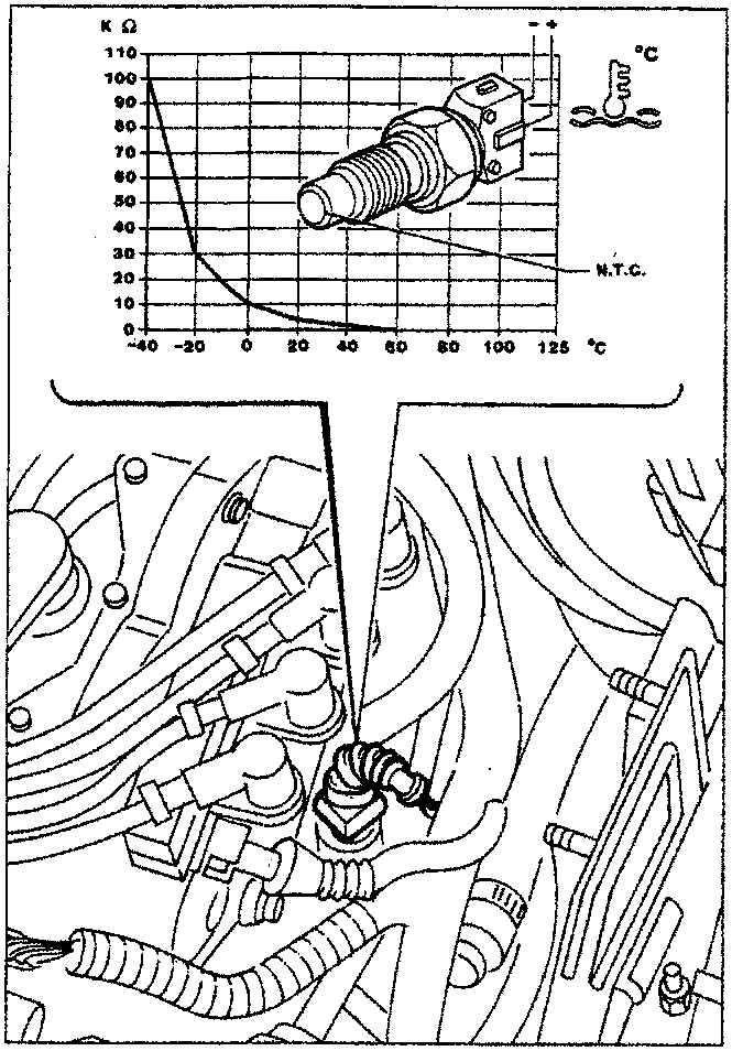
COOLANT TEMPERATURE SENSOR
(Jeager 401930.01)
The sensor is fitted to the thermostat case. It consists of a brass case, which protects the actual resistance element: an NTC thermistor (standing for Negative Temperature Coefficient because sensor electrical resistance decreases in inverse proportion to temperature).
The reference voltage is 5V; since this circuit is designed as a voltage divider, the voltage is distributed between a resistance present in the ECU and the sensor N.T.C. resistance. The ECU is therefore able at any moment to assess sensor resistance changes through voltage changes and thus obtain information on intake air temperature.
Recovery
The last reading is adopted. If the temperature does not correspond to steady state levels, this is gradually increased with time following start-up and corrected on the basis of intake air temperature.
Mixture concentration self-adaption is inhibited.
Idle self-adaption is inhibited.
Checking resistance
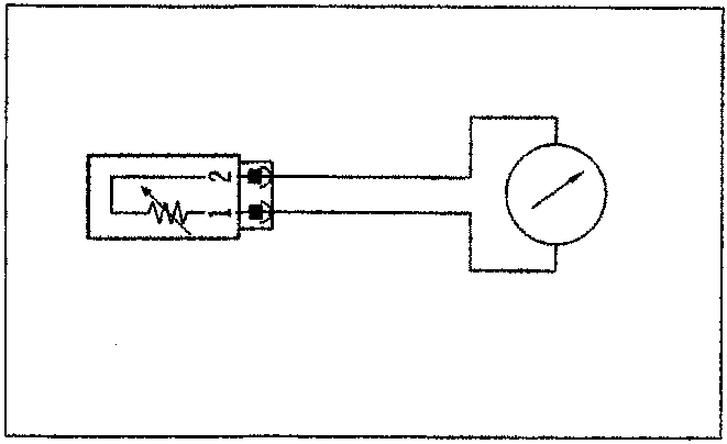
The graph plots sensor resistance values. These may be measured by disconnecting the connector and connecting an ohmmeter to the sensor terminals.
Removing-refitting
Disconnect electrical connection and remove the sensor
Before refitting apply MR/B anaerobic sealant to the tapered threads.
Tightening torque 2.4 daNm.
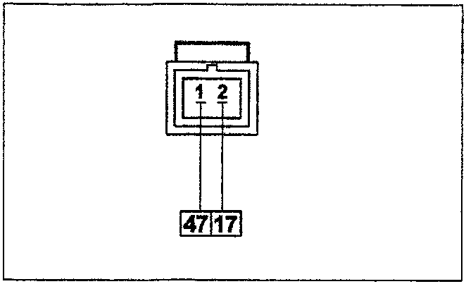
Wiring connector
The numbers in boxes indicate the corresponding control unit pins
Parts & tools for this job For 1995 Fiat Bravo
- TOOLOBD2 scannerSearch: OBD2 scanner
- TOOLDigital multimeterSearch: automotive digital multimeter
- TOOLBack-probe test leadsSearch: back probe test leads
Links open Amazon search results in a new tab. As an Amazon Associate I earn from qualifying purchases.