
Crankcase vapour/gas recirculation system
- Make
- Fiat
- Model
- Croma Factory Service Manual
- Year
- 2005–2010
- Section
- Emission control system › Crankcase vapour/gas recirculation system
CRANKCASE VAPOUR/GAS RECIRCULATION SYSTEM
SPECIFICATIONS
Function
The oil vapour emissions are controlled by means of an oil separator (1) which collects the vapours coming from the crankcase (2) and from the tappet cover (3). The condensed vapours return to the sump, via a pipe, whilst the uncondensed vapours are sent, via a pipe (5) to the turbocharger air inlet hose.
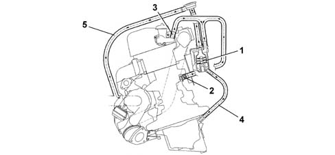
1 - Oil separator
2 - Oil vapour outlet from the crankcase
3 - Oil vapour outlet from the tappet cover
4 - Condensed vapour sump return
5 - Inlet vapour delivery pipe
6 - Regulation valve
There is a regulation valve (6), on the inlet vapour delivery pipe (5), with a spring that in normal conditions acts on a diaphragm keeping it open, thereby allowing the flow of oil vapours coming from the oil separator.
When the vacuum inside the pipe (5) overcomes the calibration of spring, the diaphragm moves thereby closing the duct from the oil vapour separator preventing the intake of oil from the sump.
SPECIFICATIONS
Function
The oil vapour emissions are controlled by the pipe (4) which collects the vapours escaping from the crankcase and the tappet cover (1) and ensures their partial condensation.
The vapours that are not condensed are sent, via the pipe (5), to the turbocharger air intake hose (3).
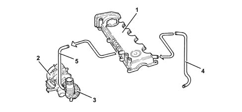
1 - Tappet cover
2 - Turbocharger
3 - Corrugated hose
4 - Oil vapour recovery pipe
5 - Oil vapour recirculation pipe
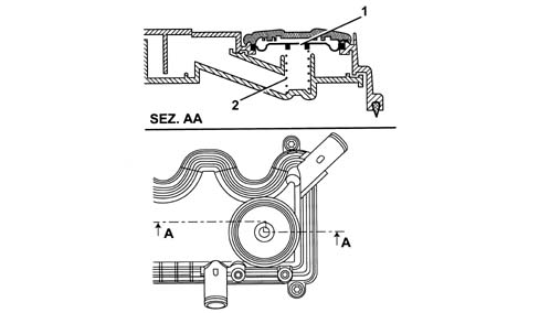
The regulation valve in the tappet cover that consists of a spring (1) and a diaphragm (2) allows the phenomenon of intake to be prevented.
When the vacuum values inside the tappet cover exceed a recommended limit, the diaphragm moves downwards sealing the duct from the crankcase.
Parts & tools for this job For 2005 Fiat Croma
- PARTExhaust gasketSearch: Fiat Croma 2005 exhaust gasket
- TOOLPenetrating oilSearch: penetrating oil
- TOOLOBD2 scannerSearch: OBD2 scanner
Links open Amazon search results in a new tab. As an Amazon Associate I earn from qualifying purchases.