
Introduction - emission control system
- Make
- Fiat
- Model
- Croma Factory Service Manual
- Year
- 2005–2010
- Section
- Emission control system › Introduction - emission control system
INTRODUCTION - EMISSION CONTROL SYSTEM
CONSTRUCTION SPECIFICATIONS
Lambda sensors
The Lambda sensor upstream of the catalytic converters is the linear type whilst the downstream one is the planar type and they notify the engine management control unit of the combustion progress (stoichiometric ratio).
The upstream sensor (? = 0.65) determines the mixture strength check (except during idling) known as the 1st closed loop (for the upstream sensor).
The sensor downstream of the catalyzer is used for the fault diagnosis of the catalyzer and for modulating the 1st loop control parameters.
The second loop is therefore adaptive to make up for production discrepancies and slight drift that upstream sensor responses could experience due to ageing and contamination.
This control is known as 2nd loop control (downstream sensor closed loop).
The electronic control unit identifies mixture composition (lean or rich) from the lambda sensor output voltage.
This adjusts injected fuel quantity to ensure optimum mixture composition (? = 1 to create ideal conditions for treatment of exhaust gas in the catalytic converter.
If the mixture is too rich (? < 1) the quantity of fuel should be reduced and if the mixture is too lean (? > 1) the quantity of fuel should be increased.
Planar Lambda sensor

a - Rich mixture (lack of air)
b - Lean mixture (excess air)
The Lambda sensors are in contact with exhaust gases and generate an electrical signal with voltage dependent on oxygen level in the gas.
This voltage changes abruptly when mixture concentration deviates from a value of ? = 1.
The injection control unit manages Lambda sensor heating in proportion with exhaust gas temperature.
This avoids thermal shocks to the ceramic case due to contact with condensed water present in exhaust gas when the engine is cold.
The measurement chamber and heater are built into a planar (laminated) ceramic element that offers the benefit of fast chamber heating. This allows closed loop (? = 1) control within 10 seconds of engine start-up.
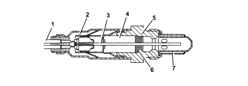
1. Connection lead
2. Protective sleeve
3. Planar sensor element
4. Ceramic support pipe
5. Sensor seat
6. Ceramic seal
7. Protective pipe
Catalytic converter
The three-way catalytic converter makes it possible to keep down the levels of the three pollutant gases in the exhaust gases at the same time:
- unburnt hydrocarbons (HC);
- carbon monoxide (CO);
- nitrogen oxides (NOx).
Two types of chemical reaction take place inside the converter:
- oxidation of CO and HC to carbon dioxide (CO2) and water (H2O)
- reduction of NOx to nitrogen (N2).
The converter consists of a structure, a metal gauze support to dampen impacts and vibrations and a stainless steel outer casing that is resistant to high temperatures and atmospheric agents.
The honeycomb structure is made from a ceramic material covered in an extermely thin layer of catalytically active substances, platinum or rhodium, which accelerated the chemical decomposition of the harmful substances contained in the exhaust gases which, when passing through the core cells at temperatures above 300° - 350°C, activate the catalyzers setting off the oxidation/reduction reactions.
A perforated steel cone improves the diffusion of the exhausts gases in the ceramic core cells to ensure the optimum efficiency and lifespan of the catalyzer.
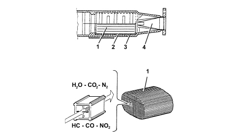
1. Ceramic structure
2. Metal support
3. Outer casing
4. Perforated steel cone
OIL VAPOUR RECIRCULATION SYSTEM (BLOW-BY)
The system controls the vapour emissions, coming from the crankcase, made up of an air/petrol mixture, unburnt gases that escape from the piston seals and lubricant oil vapours recirculating them to the intake.
There is a labyrinth inside the tappet cover through which some of the gases are condensed to the oil sump.
As a result of the vacuum created following the opening of the throttle, the remaining gases are drawn into the combustion chamber together with the fresh charge and they are eliminated following subsequent combustion.
EVAPORATION CONTROL SYSTEM
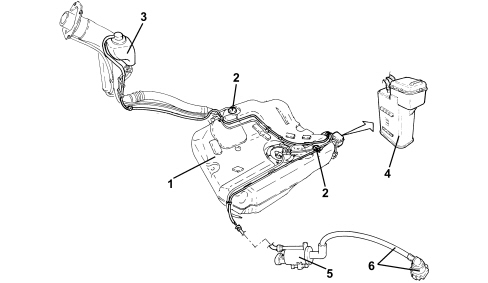
The vapours coming from the tank (1) are sent, via the two float valves (2) to the separator (3) where they are partly condensed.
The residual fuel vapours are sent, by means of special pipes, to the canister (4) where they are absorbed by and stored in the active charcoal.
The vapours flow to the intake manifold through a special pipe (6) in the solenoid by means of the solenoid (5) controlled by the injection control unit.
Canister
This is fitted to the left rear wheel arch and consists of an activated carbon filter element that absorbs fuel vapours from the separator.
An opening in the canister allows the intake of air and is like a labyrinth to prevent the intake of water.
The fuel vapour inlet and outlet pipes are thermowelded onto the canister and cannot therefore be dismantled.
Fuel vapour solenoid valve
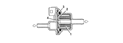
This is fitted on the upper part of the air chamber and is controlled by the injection control unit.
The solenoid allows fuel vapours stored in the canister to flow through to the engine intake.
If deactivated, the solenoid remains in open position. At key-ON, it closes ready for operation.
The electromagnet (1), if energized, attracts the shutter (2) that overcomes the loading of the spring pack (3) to close the opening (4) and prevent fuel vapours from passing through.
INTRODUCTION
The emission control system includes the devices designed to reduce atmospheric levels of harmful emissions.
The main emissions caused by the car are:
- exhaust emissions;
- vapour/gas emissions from the crankcase;
- fuel vapour emissions.
EXHAUST EMISSIONS
Lambda sensors
The Lambda sensor upstream of the catalytic converters is the linear type whilst the downstream one is the planar type and they notify the engine management control unit of the combustion progress (stoichiometric ratio).
The upstream sensor (? = 0.65) determines the mixture strength check (except during idling) known as the 1st closed loop (for the upstream sensor).
The sensor downstream of the catalyzer is used for the fault diagnosis of the catalyzer and for modulating the 1st loop control parameters.
The second loop is therefore adaptive to make up for production discrepancies and slight drift that upstream sensor responses could experience due to ageing and contamination.
This control is known as 2nd loop control (downstream sensor closed loop).
The electronic control unit identifies mixture composition (lean or rich) from the lambda sensor output voltage.
This adjusts injected fuel quantity to ensure optimum mixture composition (? = 1 to create ideal conditions for treatment of exhaust gas in the catalytic converter.
If the mixture is too rich (? < 1) the quantity of fuel should be reduced and if the mixture is too lean (? > 1) the quantity of fuel should be increased.
Planar Lambda sensor
a - Rich mixture (lack of air)
b - Lean mixture (excess air)
The Lambda sensors are in contact with exhaust gases and generate an electrical signal with voltage dependent on oxygen level in the gas.
This voltage changes abruptly when mixture concentration deviates from a value of ? = 1.
The injection control unit manages lambda sensor heating in proportion with exhaust gas temperature.
This avoids thermal shocks to the ceramic case due to contact with condensed water present in exhaust gas when the engine is cold.
The measurement chamber and heater are built into a planar (laminated) ceramic element that offers the benefit of fast chamber heating. This allows closed loop (? = 1) control within 10 seconds of engine start-up.
1. Connection lead
2. Protective sleeve
3. Planar sensor element
4. Ceramic support pipe
5. Sensor seat
6. Ceramic seal
7. Protective pipe
Catalytic converter
The three-way catalytic converter makes it possible to keep down the levels of the three pollutant gases in the exhaust gases at the same time:
- unburnt hydrocarbons (HC);
- carbon monoxide (CO);
- nitrogen oxides (NOx).
Two types of chemical reaction take place inside the converter:
- oxidation of CO and HC to carbon dioxide (CO2) and water (H2O)
- reduction of NOx to nitrogen (N2).
The converter consists of a structure, a metal gauze support to dampen impacts and vibrations and a stainless steel outer casing that is resistant to high temperatures and atmospheric agents.
The honeycomb structure is made from a ceramic material covered in an extermely thin layer of catalytically active substances, platinum or rhodium, which accelerated the chemical decomposition of the harmful substances contained in the exhaust gases which, when passing through the core cells at temperatures above 300° - 350°C, activate the catalyzers setting off the oxidation/reduction reactions.
A perforated steel cone improves the diffusion of the exhausts gases in the ceramic core cells to ensure the optimum efficiency and lifespan of the catalyzer.
1. Ceramic structure
2. Metal support
3. Outer casing
4. Perforated steel cone
CRANKCASE VAPOUR/GAS EMISSIONS
The system controls the vapour emissions, coming from the crankcase, made up of an air/petrol mixture, unburnt gases that escape from the piston seals and lubricant oil vapours recirculating them to the intake.
There is a labyrinth inside the tappet cover through which some of the gases are condensed to the oil sump.
As a result of the vacuum created following the opening of the throttle, the remaining gases are drawn into the combustion chamber together with the fresh charge and they are eliminated following subsequent combustion.
FUEL VAPOUR EMISSIONS
Evaporation control system
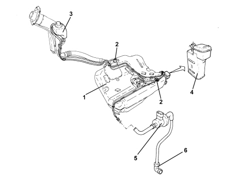
The vapours coming from the tank (1) are sent, via the two float valves (2) to the separator (3) where they are partly condensed.
The residual fuel vapours are sent, by means of special pipes, to the canister (4) where they are absorbed by and stored in the active charcoal.
The vapours flow to the intake manifold through a special pipe (6) in the solenoid by means of the solenoid (5) controlled by the injection control unit.
Canister
This is fitted to the left side of the fuel tank and consists of an activated carbon filter element that absorbs fuel vapours from the separator.
An opening in the canister allows the intake of air and is like a labyrinth to prevent the intake of water.
The fuel vapour inlet and outlet pipes are thermowelded onto the canister and cannot therefore be dismantled.
Fuel vapour solenoid valve
This is fitted on the upper part of the modular intake chamber and is controlled by the injection control unit.
The solenoid allows fuel vapours stored in the canister to flow through to the engine intake.
If the power is off, the solenoid is closed and prevents fuel vapours from enriching the mixture excessively.
The solenoid valve is controlled by the injection control unit depending on given parameters such as the engine load.
When electromagnet inside the valve is energized, it attracts valve core which overcomes the load of spring bringing the canister in contact with the modular intake manifold.
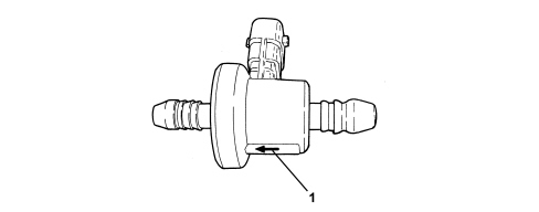
1. Direction of fuel vapour flow
When fitting the fuel vapour solenoid valve, avoid positioning the electrical connector towards the bottom.

Parts & tools for this job For 2005 Fiat Croma
- PARTExhaust gasketSearch: Fiat Croma 2005 exhaust gasket
- TOOLPenetrating oilSearch: penetrating oil
- TOOLOBD2 scannerSearch: OBD2 scanner
Links open Amazon search results in a new tab. As an Amazon Associate I earn from qualifying purchases.