
Introduction - timing system
- Make
- Fiat
- Model
- Grande Punto Factory Service Manual
- Year
- 2005–2012
- Section
- Timing system › Introduction - timing system
INTRODUCTION - TIMING SYSTEM
SPECIFICATIONS
A cast iron overhead camshaft operated by a timing belt.
COMPOSITION
There are the same number of suitably positioned, profiled cams on the shaft as the valves to be operated; at the front there is provision for fitting a toothed pulley through which to receive movement from the crankshaft by means of a suitably tensioned timing belt.
On the 1.4 8v version the toothed pulley is incorporated in the phase transformer described below.
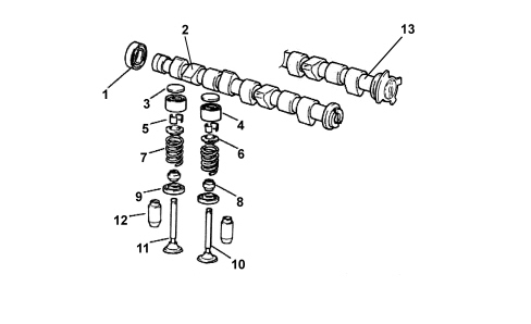
1. Crankshaft oil seal
2. Camshaft (1.2 8v version)
3. Tappet adjustment shim
4. Tappets
5. Cotters
6. Upper shim
7. Spring
8. Oil seal
9. Lower shim
10. Inlet valve
11. Exhaust valve
12. Valve guide
13. Camshaft with phonic wheel (1.4 8v version)
PHASE TRANSFORMER (1.4 8v version only)
Specifications
The 1.4 8v EVO2 engine is equipped with a "continuous" phase transformer capable of modifying the position of the camshaft in relation to the crankshaft.
In this way the engine is working with optimum timing in all operating points.
The phase transformer is managed entirely by the engine management control unit which:
- detects the camshaft position via the timing sensor;
- alters this position according to the engine operation on the basis of a calibrated map;
- keeps the camshaft position under control.
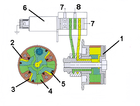
1. Driven pulley
2. Stator
3. Advance compartment
4. Delay compartment
5. Rotor
6. Cassette solenoid valve
7. Oil return
8. Oil inlet
Operation
The phase transformer actuator comprises a rotor in one piece with the camshaft that can rotate in relation to the pulley (stator) moved by the crankshaft. The rotor is equipped with vanes and moves through the effect of the engine oil pressure on the vanes.
There are two compartments (the advance compartment and the delay compartment) created at the two sides of each of these vanes: the oil can flow into one compartment or the other.
The pressure of the oil entering a compartment pushes the vane to one side and the oil in the other compartment is discharged to the cylinder head. The rotor is and consequently the camshaft are thereby rotated in a certain direction (advance or delay).
If the engine oil alternatively enters one compartment and the other continuously for the same time, the pressures at the two sides of the rotor are dynamically balanced and it remains still.
The flow of engine oil is activated by a cassette solenoid valve which places the oil ducts in the cylinder head in contact with the advance or delay compartments.
SPECIFICATIONS
Two, ductile cast iron, overhead camshafts in a camshaft housing; they are operated by a belt and gears.
COMPOSITION
There are suitably directed cams on the camshafts with suitable profiles, in the same number as the valves to be operated.
The exhaust shaft is prepared at the front for the fitting of the toothed pulley/phase transformer by means of which it receives movement from the crankshaft by means of the toothed belt.
A pair of gears, fitted at the behind the shafts, allows the transfer of power from the exhaust shaft to the inlet shaft.
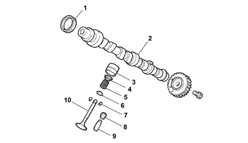
1, Camshaft oil seal
2, Camshaft
3, Tappet
4, Upper shim
5, Spring
6, Lower shim
7, Cotters
8, Oil seal
9, Valve guide
10, Valve
HYDRAULIC TAPPETS
The hydraulic tappets used on this engine type automatically take up valve clearance during engine service. This offers the advantage of reducing:
- maintenance operations
- engine noise.
Operation in open stage
When the camshaft cam acts on the cup (1) and thus the piston (2), the oil trapped in the chamber (6) due to the closure of the ball valve (4) trasmits the movement of the piston (2) directly to the hose (3) and consequently to the valve. At this stage, due to the high pressure acting on the oil, some of the oil in the chamber (6) leaks through the tiny gap between the piston (2) and the hose (3).
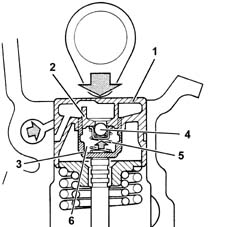
Operation in closed stage
During valve closure, as long as the tappet pressed by the action of spring (5) follows the cam outline, a vacuum builds up inside chamber (6) that brings about opening of ball valve (6) to allow oil to enter. The oil taken into chamber (6) replaces the oil that leaked out during valve opening.
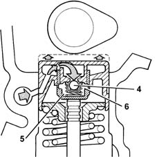
PHASE TRANSFORMER
Specifications
The "continuous" phase transformer is capable of modifying the position of the camshaft in relation to the crankshaft.
In this way the engine is working with optimum timing in all operating points.
The phase transformer is managed entirely by the engine management control unit which:
- detects the camshaft position via the timing sensor;
- alters this position according to the engine operation on the basis of a calibrated map;
- keeps the camshaft position under control.
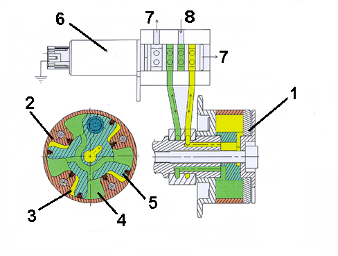
1. Driven pulley
2. Stator
3. Advance compartment
4. Delay compartment
5. Rotor
6. Cassette solenoid valve
7. Oil return
8. Oil inlet
Operation
The phase transformer actuator comprises a rotor in one piece with the camshaft that can rotate in relation to the pulley (stator) moved by the crankshaft. The rotor is equipped with vanes and moves through the effect of the engine oil pressure on the vanes.
There are two compartments (the advance compartment and the delay compartment) created at the two sides of each of these vanes: the oil can flow into one compartment or the other.
The pressure of the oil entering a compartment pushes the vane to one side and the oil in the other compartment is discharged to the cylinder head. The rotor is and consequently the camshaft are thereby rotated in a certain direction (advance or delay).
If the engine oil alternatively enters one compartment and the other continuously for the same time, the pressures at the two sides of the rotor are dynamically balanced and it remains still.
The flow of engine oil is activated by a cassette solenoid valve which places the oil ducts in the cylinder head in contact with the advance or delay compartments.
Parts & tools for this job For 2005 Fiat Grande Punto
- PARTEngine gasket setSearch: Fiat Grande Punto 2005 engine gasket set
- TOOLTorque wrenchSearch: 3/8 inch torque wrench
- TOOLFeeler gauge setSearch: feeler gauge set
Links open Amazon search results in a new tab. As an Amazon Associate I earn from qualifying purchases.