
Blower controls – circuit diagram
- Make
- Land Rover
- Model
- Discovery Electrical Troubleshooting Manual
- Year
- 1995
- Section
- Circuit diagram › Blower controls – circuit diagram
Blower controlsBlower controls – circuit diagram
BLOWER CONTROLS – CIRCUIT DIAGRAM
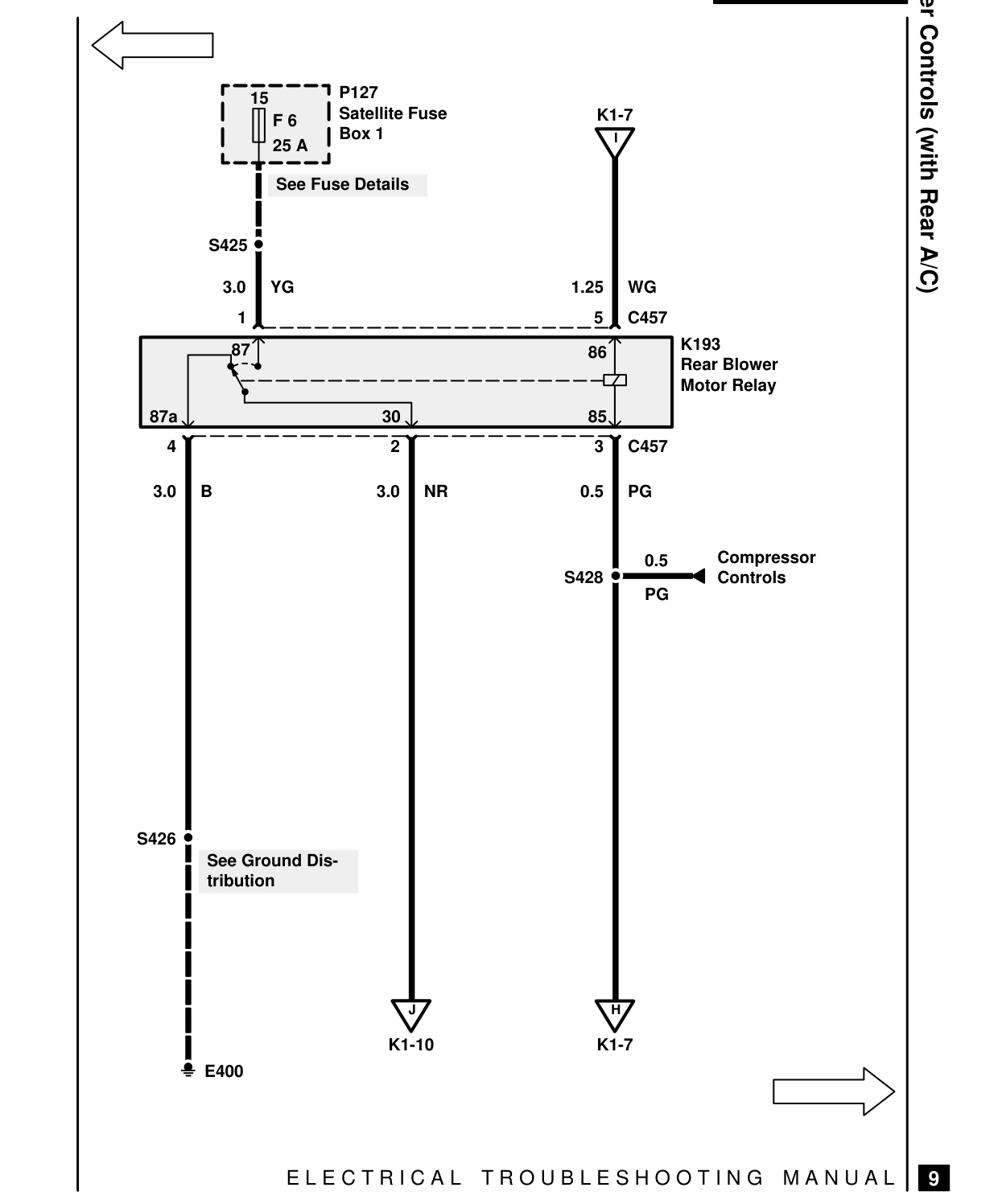
P127 15 Satellite Fuse F 6 Box 1 25 A
See Fuse Details
S425
3.0 YG 1 87
87a 30 4 2
3.0 B 3.0 NR
S426 See Ground Dis- tribution
J
K1-10 E400
E L E C T R I C A L
Blower Controls (with Rear A/C) K1-7 I
1.25 WG 5 C457 K193 86 Rear Blower Motor Relay 85 3 C457
0.5 PG
Compressor 0.5 S428 Controls PG
H
K1-7
T R O U B L E S H O O T I N G M A N U A L
9
Parts & tools for this job For 1995 Land Rover Discovery
- TOOLA/C manifold gauge setSearch: AC manifold gauge set
- TOOLUV leak detection kitSearch: AC UV leak detection kit
- PARTCabin filterSearch: Land Rover Discovery 1995 cabin filter
Links open Amazon search results in a new tab. As an Amazon Associate I earn from qualifying purchases.