
Compressor controls – circuit diagram
- Make
- Land Rover
- Model
- Discovery Electrical Troubleshooting Manual
- Year
- 1995
- Section
- Circuit diagram › Compressor controls – circuit diagram
Compressor controlsCompressor controls – circuit diagram
COMPRESSOR CONTROLS – CIRCUIT DIAGRAM
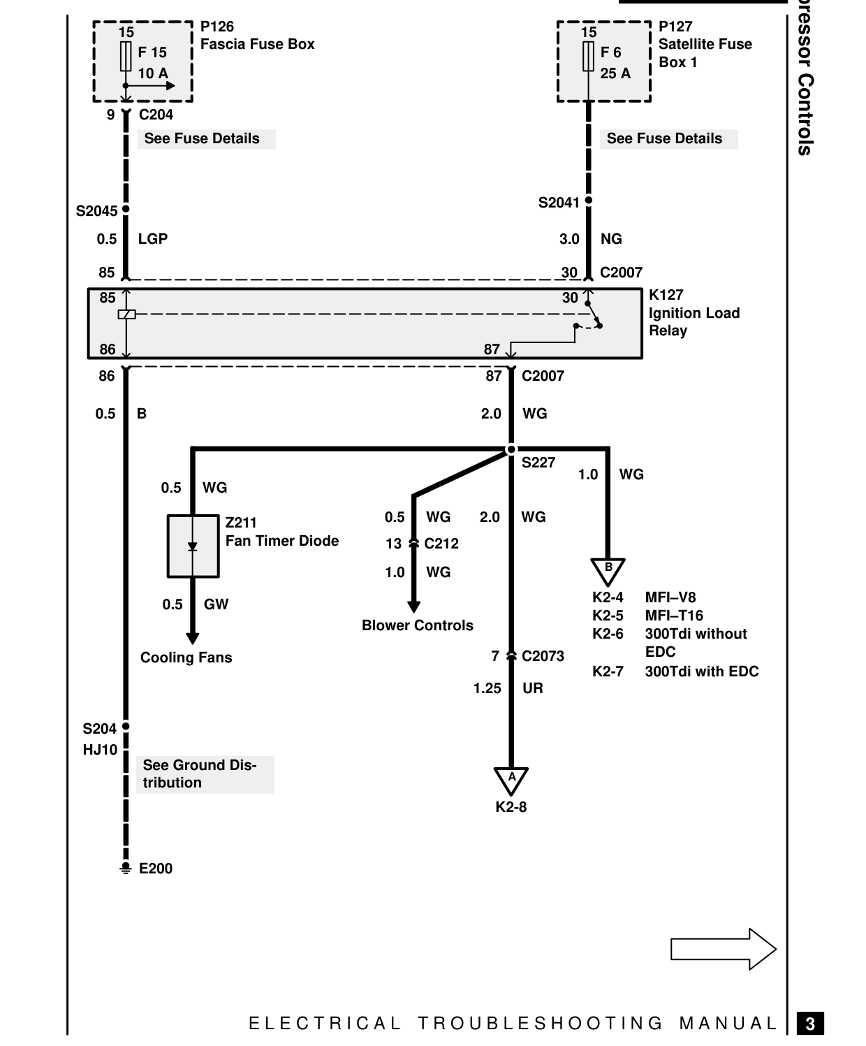
P126 15 Fascia Fuse Box F 15 10 A
9 C204 See Fuse Details
S2045 0.5 LGP
85 85
86 86
0.5 B
0.5 WG
0.5 Z211 Fan Timer Diode 13 1.0
0.5 GW Blower Controls
Cooling Fans
S204 HJ10 See Ground Dis- tribution
E200
E L E C T R I C A L
Compressor Controls P127 15 Satellite Fuse F 6 Box 1 25 A
See Fuse Details
S2041
3.0 NG
30 C2007 K127 30 Ignition Load Relay 87 87 C2007
2.0 WG
S227 1.0 WG
WG 2.0 WG C212 B WG K2-4 MFI-V8 K2-5 MFI-T16 K2-6 300Tdi without EDC 7 C2073 K2-7 300Tdi with EDC 1.25 UR
A
K2-8
T R O U B L E S H O O T I N G M A N U A L
3
Parts & tools for this job For 1995 Land Rover Discovery
- TOOLDigital multimeterSearch: automotive digital multimeter
- PARTAssorted fuse kitSearch: car fuse assortment kit
- TOOLWire crimper and connector kitSearch: wire crimper connector kit
Links open Amazon search results in a new tab. As an Amazon Associate I earn from qualifying purchases.