
Cooling fans – circuit diagram
- Make
- Land Rover
- Model
- Discovery Electrical Troubleshooting Manual
- Year
- 1995
- Section
- Circuit diagram › Cooling fans – circuit diagram
Cooling fansCooling fans – circuit diagram
COOLING FANS – CIRCUIT DIAGRAM
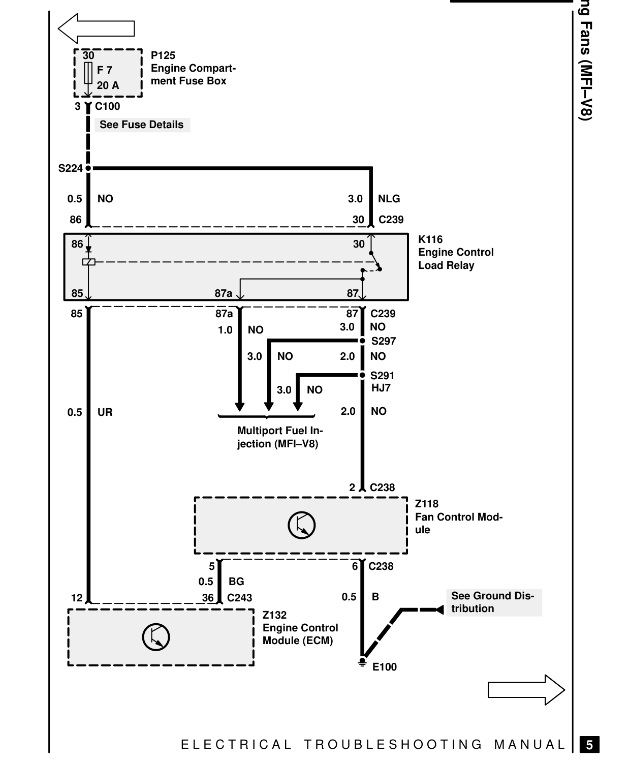
P125 30 Engine Compart- F 7 ment Fuse Box 20 A 3 C100 See Fuse Details
S224
0.5 NO 86
86
85 87a 85 87a 1.0 NO
3.0 NO
3.0
0.5 UR Multiport Fuel In- jection (MFI-V8)
5 0.5 BG 36 C243 12 Z132 Engine Control Module (ECM)
E L E C T R I C A L
Cooling Fans (MFI-V8)
3.0 NLG 30 C239 K116 30 Engine Control Load Relay
87 C239 87 3.0 NO S297 2.0 NO S291 HJ7 NO
2.0 NO
C238 2 Z118 Fan Control Mod- ule
C238 6
See Ground Dis- 0.5 B tribution
E100
T R O U B L E S H O O T I N G M A N U A L
5
Parts & tools for this job For 1995 Land Rover Discovery
- TOOLDigital multimeterSearch: automotive digital multimeter
- PARTAssorted fuse kitSearch: car fuse assortment kit
- TOOLWire crimper and connector kitSearch: wire crimper connector kit
Links open Amazon search results in a new tab. As an Amazon Associate I earn from qualifying purchases.