
Engine management system - siemens (all except NAS) (Fuel Injectors): Description and operation
- Make
- Land Rover
- Model
- Freelander System Description and Operation (UK)
- Section
- Description and operation › Fuel Injectors
Fuel Injectors
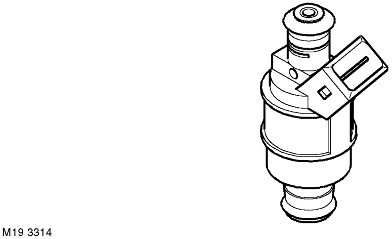
A split stream, air assisted fuel injector is installed for each cylinder. The injectors are located in the inlet manifolds and connected to a common fuel rail assembly.
Each injector contains a pintle type needle valve and a solenoid winding. The needle valve is held closed by a return spring. An integral nozzle shroud contains a ported disc, adjacent to the nozzles. 'O' rings seal the injector in the fuel rail and the inlet manifold.
The solenoid winding of each injector receives a 12 volt supply from the main relay. To inject fuel, the ECM supplies an earth path to the solenoid winding, which energises and opens the needle valve. When the needle valve opens, the two nozzles direct a spray of atomised fuel onto the back of each inlet valve. Air drawn through the shroud and ported disc improves atomisation and directional control of the fuel. The air is supplied from a dedicated port in the IAC valve via a plastic tube and tracts formed in the gasket face of the intake manifolds.
Each injector delivers fuel once per engine cycle, during the inlet stroke. The ECM calculates the open time (duty cycle) of the injectors from: l Engine speed. l Mass air flow. l Engine temperature. l Throttle position.
The fuel in the fuel rail is maintained at a pressure of 3.5 bar (51 lbf/in2) by a pressure regulator incorporated into the pump unit in the fuel tank. An accumulator is attached to the fuel rail on the RH inlet manifold to damp out pressure pulses from the pump and ensure that the pressure in the fuel rail is constant (the same component functions as the pressure regulator on vehicles with a return fuel delivery system). The accumulator is connected by a pipe to the inlet manifold from which it receives a vacuum to aid the damping process. A Schraeder valve is installed in the 'fuel return' pipe of the accumulator to allow pressure to be released from the fuel rail and fuel feed pipe prior to maintenance.
The nominal resistance of the injector solenoid winding is 13 - 16 Ω at 20 °C (68 °F).
Parts & tools for this job For Land Rover Freelander
- PARTFuel filterSearch: Land Rover Freelander fuel filter
- TOOLFuel pressure test kitSearch: fuel pressure test kit
- TOOLFuel line disconnect toolSearch: fuel line disconnect tool
Links open Amazon search results in a new tab. As an Amazon Associate I earn from qualifying purchases.