
Engine management system - siemens (all except NAS) (Warning Lamp): Description and operation
- Make
- Land Rover
- Model
- Freelander System Description and Operation (UK)
- Section
- Description and operation › Warning Lamp
Warning Lamp
The warning lamp indicates the status of the cruise control system. Located in the instrument pack, the warning lamp illuminates when cruise control is engaged, and consists of a motorway graphic on a yellow background (all except NAS) or a yellow CRUISE legend (NAS only).
Vacuum Pump Assembly
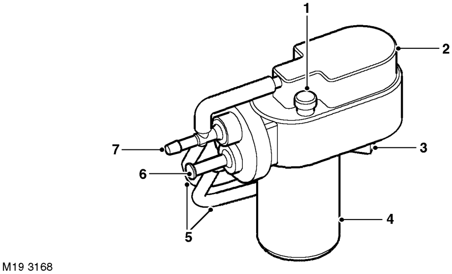
1 Vent 2 Valve housing 3 Electrical connector 4 Motor housing
5 Connecting hoses 6 Vent 7 Vacuum actuator connection
The vacuum pump assembly controls the operation of the vacuum actuator. The assembly is installed in the LH front corner of the engine compartment, on mounting rubbers attached to the front of the battery box. The assembly consists of a vacuum pump, driven by an electric motor, and two normally open solenoid valves: a control valve and a dump valve. Connecting hoses link the outlets of the control valve and the dump valve to the inlet side of the vacuum pump, at a vacuum actuator connection. A further connecting hose links the inlet side of the control valve to the outlet side of the vacuum pump at a common vent. A second vent is provided for the inlet to the dump valve. A non return valve between the vacuum pump and the vacuum actuator connection prevents the reverse flow of air through the vacuum pump. An electrical connector on the underside of the valve housing connects the vacuum pump assembly to the cruise control ECU and the brake pedal switch via the vehicle wiring.
Parts & tools for this job For Land Rover Freelander
- PARTReplacement bulbsSearch: Land Rover Freelander bulbs
- TOOLDigital multimeterSearch: automotive digital multimeter
Links open Amazon search results in a new tab. As an Amazon Associate I earn from qualifying purchases.