
Vacuum System Schematic
- Make
- Land Rover
- Model
- Freelander System Description and Operation (UK)
- Section
- Description and operation › Vacuum System Schematic
Vacuum System Schematic
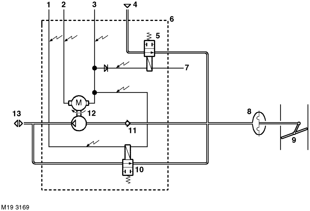
1 Control valve control signal 2 Vacuum pump control signal 3 Vacuum pump and valves supply 4 Vent 5 Dump valve 6 Vacuum pump assembly 7 Dump valve control signal
8 Vacuum actuator 9 Throttle 10 Control valve 11 Non return valve 12 Vacuum pump 13 Vent
When cruise control is selected and the vehicle is in the correct driving configuration, the cruise control ECU outputs the pump and valves power supply. The cruise control ECU also closes the control and dump valves, and runs the vacuum pump, using individual Pulse Width Modulated (PWM) control signals.
When the vacuum pump runs, it draws air through the non return valve and creates a depression on one side of the diaphragm in the vacuum actuator, which moves to open the throttle. When the vehicle is at the set speed, the cruise control ECU stops the vacuum pump, and the non return valve closes to maintain the depression in the vacuum actuator and hold the throttle in position. If vehicle speed decreases below the set speed, or a higher set speed is required, the cruise control ECU starts the vacuum pump again to increase the depression in the vacuum actuator and increase the throttle angle. If the vehicle speed increases above the set speed, the cruise control ECU opens the control valve to reduce the depression in the vacuum actuator and reduce the throttle angle.
When cruise control is disengaged, the cruise control ECU removes the pump and valves power supply from the vacuum pump assembly, to disable the vacuum pump and open the control and dump valves. The open valves allow atmospheric pressure into the vacuum actuator, which moves to close the throttle. The dump valve provides additional safety for the system, by ensuring the vacuum is released from the vacuum actuator even if the control valve remains closed or the control valve vent line is obstructed.
Parts & tools for this job For Land Rover Freelander
- PARTEngine gasket setSearch: Land Rover Freelander engine gasket set
- TOOLTorque wrenchSearch: 3/8 inch torque wrench
- TOOLFeeler gauge setSearch: feeler gauge set
Links open Amazon search results in a new tab. As an Amazon Associate I earn from qualifying purchases.