
Fuel system - MPi (page 4 of 7)
- Make
- MG
- Model
- MGF Factory Workshop Manual
- Year
- 1995–2000
- Section
- Description and operation
Engine management system - MEMSFuel system - MPi · page 4 of 7
Engine management relay module
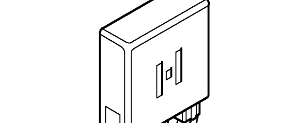
The relay module is located on the bulkhead in the engine compartment behind the engine control module. The relay module contains the following relays:
- Main relay - energised when the ignition is switched on and supplies power to the ECM.
- Fuel pump relay - energised by the ECM for a short period when the ignition is switched on, during cranking and while the engine is running.
- Starter relay - energised by the cranking signal from the ignition switch.
- Heated oxygen sensor relay - energised by the ECM and supplies current to the heated oxygen sensor element.
Fuel pump
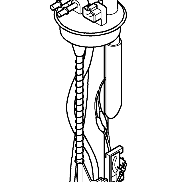
The electric fuel pump is located inside the fuel tank and is energised by the ECM via the fuel pump relay in the relay module and the fuel cut-off inertia switch.
The fuel pump delivers more fuel than the maximum load requirement for the engine, pressure is therefore maintained in the fuel system under all conditions.
Parts & tools for this job For 1995 MG MGF
- PARTFuel filterSearch: MG MGF 1995 fuel filter
- TOOLFuel pressure test kitSearch: fuel pressure test kit
- TOOLFuel line disconnect toolSearch: fuel line disconnect tool
Links open Amazon search results in a new tab. As an Amazon Associate I earn from qualifying purchases.