
Engine and automatic gearbox assembly (page 6 of 8)
- Make
- Rover
- Model
- 100 Repair Manual Supplement
- Year
- 1996–1998
- Section
- Repairs
EngineEngine and automatic gearbox assembly · page 6 of 8
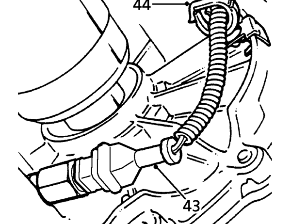
- Disconnect inhibitor switch multiplug.
- Release inhibitor switch harness from clip on gearbox case.
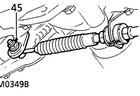
- Loosen nut securing selector cable rod to selector lever.
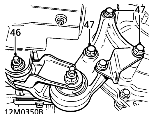
- Remove bolt securing engine steady bar to body.
- Remove 3 bolts securing engine steady bar bracket to gearbox.
- Release selector cable rod and steady bar.
- Drain gearbox fluid. See REPAIR MANUAL - Maintenance.
- Drain engine oil if required. See REPAIR MANUAL - Maintenance.
- Remove both drive shaft and hub assemblies. See REPAIR MANUAL - Automatic Gearbox - Differential Oil Seal.
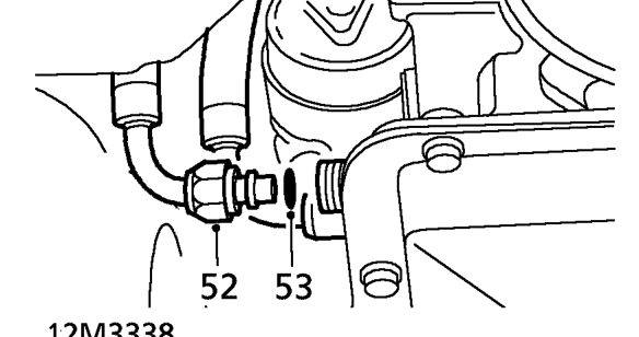
- Disconnect fluid cooler hose connections from adapters on gearbox.
CAUTION: Plug the connections.
- Discard ’O’ rings and position hoses aside.
Parts & tools for this job For 1996 Rover 100
- PARTEngine gasket setSearch: Rover 100 1996 engine gasket set
- TOOLTorque wrenchSearch: 3/8 inch torque wrench
- TOOLFeeler gauge setSearch: feeler gauge set
Links open Amazon search results in a new tab. As an Amazon Associate I earn from qualifying purchases.