
’H’ frame - models with disc brakes (page 4 of 4)
- Make
- Rover
- Model
- 200 Workshop Manual
- Year
- 1995–1999
- Section
- Repairs
Rear suspension’H’ frame - models with disc brakes · page 4 of 4
Do not carry out further dismantling if component is removed for access only.
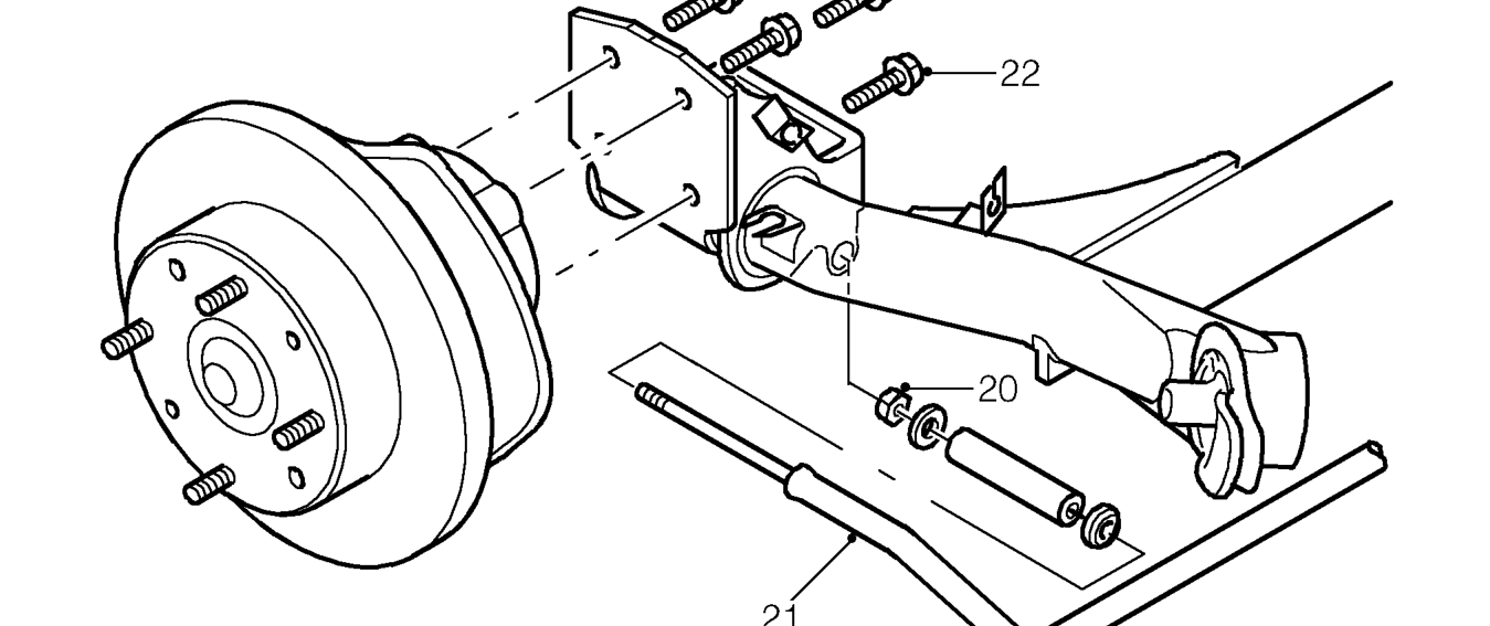
- Remove 2 nuts securing anti-roll bar to ’H’ frame.
- Remove anti-roll bar from ’H’ frame.
- Remove 4 bolts securing each hub/stub axle assembly to ’H’ frame and remove hubs.
- Position hub/stub axle assembly to new ’H’ frame and tighten bolts to 45 Nm.
- Fit anti-roll bar to ’H’ frame and tighten nuts to 80 Nm.
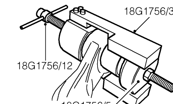
- Position new pivot bush to ’H’ frame and fit tools 18G 1756/12, 18G 1756/3 and 18G 1756/5 as shown in illustration.
- Rotate handle of tool to press bush into ’H’ frame and remove tools.
- Fit second pivot bush to ’H’ frame.
Parts & tools for this job For 1995 Rover 200
- PARTRear brake padsSearch: Rover 200 1995 rear brake pads
- TOOLCaliper piston rewind toolSearch: brake caliper piston rewind tool
- FLUIDBrake fluidSearch: brake fluid
Links open Amazon search results in a new tab. As an Amazon Associate I earn from qualifying purchases.