
Power steering rack - ’d’ series (page 2 of 3)
- Make
- Rover
- Model
- 400 Workshop Manual
- Year
- 1995–2000
- Section
- Repairs
SteeringPower steering rack - ’d’ series · page 2 of 3
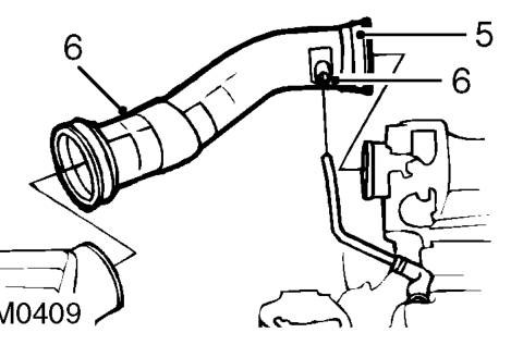
- Loosen clip securing air intake hose to inlet manifold and release clip securing intake hose to breather pipe.
- Disconnect hose from manifold and breather pipe and remove hose from air cleaner.
- Remove exhaust front pipe. See MANIFOLD & EXHAUST SYSTEMS, Repairs.
- Remove bolt securing selector cable support bracket to front beam.
- Remove 2 bolt securing selector cable cover to gearbox and remove cover.
- Release lock washer and remove bolt securing selector cable to gearbox. Discard lock washer.
- Release selector cable from gearbox.
- Remove road wheel(s).
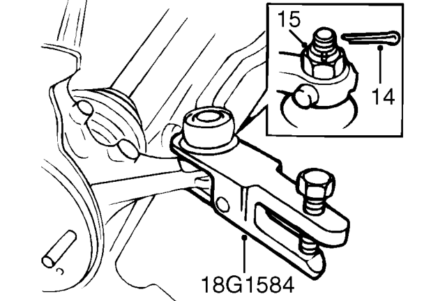
- Slacken RH and LH tie-rod end locknuts.
- Remove split pins from each tie-rod end ball joint nut. Discard split pins.
- Remove 2 ball joint nuts and break taper joints using tool 18G 1584 .
- Note number of threads exposed from each locknut, for refitting reference and remove 2 tie-rod ends.
- Extend steering rack fully to passenger’s side.
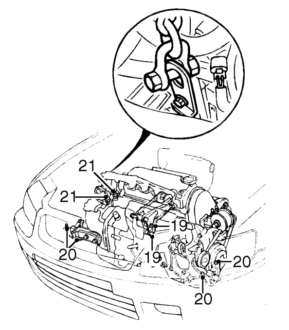
- Attach lifting chain to gearbox bracket and support engine weight.
- Remove 4 bolts securing rear centre engine mounting to gearbox case.
- Remove 4 bolts securing front RH and LH engine mounting to body.
- Remove 2 nuts RH centre engine mounting.
- Lower engine and gearbox assembly 50 - 60 mm.
Parts & tools for this job For 1995 Rover 400
- TOOLTie rod end toolSearch: tie rod end puller
- TOOLBall joint separatorSearch: ball joint separator
- FLUIDPower steering fluidSearch: Rover power steering fluid
Links open Amazon search results in a new tab. As an Amazon Associate I earn from qualifying purchases.