
Control by increasing caliper fluid pressure (page 2 of 2)
- Make
- Rover
- Model
- 600 Rover 600 Repair Manual - Volumes 1 and 2 - 2nd Edition
- Section
- Operation
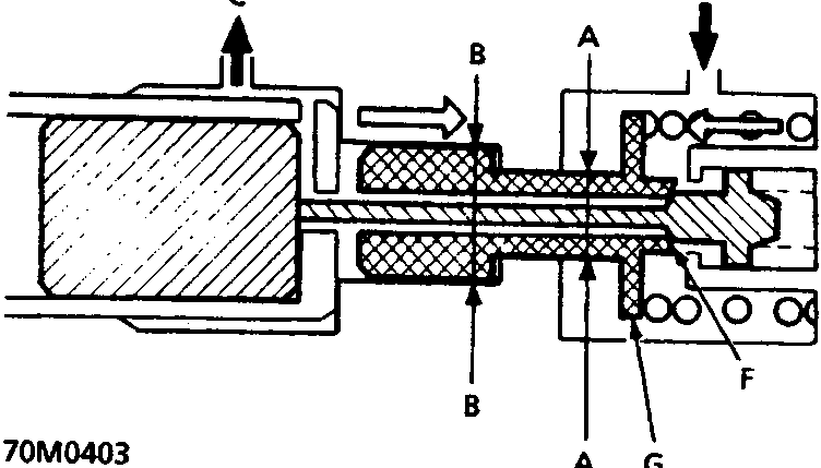
- A Section where pressure from master cylinder is applied
- B Section where pressure from rear caliper is applied
- C to rear brake caliper
- D from master cylinder
- E Spring force
- F Cut valve – closed
- G Cut valve seat
To prevent the rear wheels from locking, the proportioning control valve function changes the distribution rate of the fluid pressure to the rear wheels when the pressure in the rear brake system exceeds the given value of the fluid pressure from the master cylinder. The fluid pressure point where the distribution rate changes is called the Turning Point.
The cut valve seat in the rear brake system has a shoulder between sections A and B. Section A, where pressure from the master cylinder is applied, has a smaller diameter than section B, where pressure from the rear brake calipers applied. This arrangement provides the proportioning control valve function as follows.
- When the fluid pressure from the master cylinder is below the Turning Point, the cut valve seat is pushed by the spring force and the cut valve is open. Therefore, the fluid pressure from the master cylinder is transmitted to the rear brake caliper side. Under these conditions, fluid pressure from the master cylinder is equal to the pressure to the rear brake caliper, but because of the diameter difference between section A and B, the force on the cut valve overcomes the spring force, moving the cut valve seat slowly towards the cut valve.
- When the fluid pressure to the rear brake caliper reaches the Turning Point, the cut valve is closed by the cut valve seat, blocking the fluid passage between the master cylinder side and rear wheel cylinder side.
- When fluid pressure from the master cylinder exceeds the Turning Point, the fluid pressure from the master cylinder rises, while the pressure to the rear brake caliper remains at the Turning Point value. As a result, the cut valve seat moves away from the cut valve and the cut valve opens. The passage between the master cylinder and the caliper opens momentarily, but it is blocked again because the fluid pressure to the brake caliper rises, and the cut valve seat moves to close the cut valve. As explained above, when the pressure in the master cylinder is above the Turning Point, the cut valve seat reduces the pressure in the rear brake caliper to the prescribed amount by repeating the process.
Parts & tools for this job For Rover 600
- PARTBrake padsSearch: Rover 600 brake pads
- TOOLCaliper piston rewind toolSearch: brake caliper piston rewind tool
- FLUIDBrake fluidSearch: brake fluid
Links open Amazon search results in a new tab. As an Amazon Associate I earn from qualifying purchases.