
Fault Finding Intermittent Failures (page 2 of 4)
- Make
- Rover
- Model
- 600 Rover 600 Repair Manual - Volumes 1 and 2 - 2nd Edition
- Section
- Fault finding
Supplementary restraint system (SRS)Fault Finding Intermittent Failures · page 2 of 4
Note: Use only the short connector. It may not be possible to connect and disconnect a jumper wire quickly enough to erase the memory.
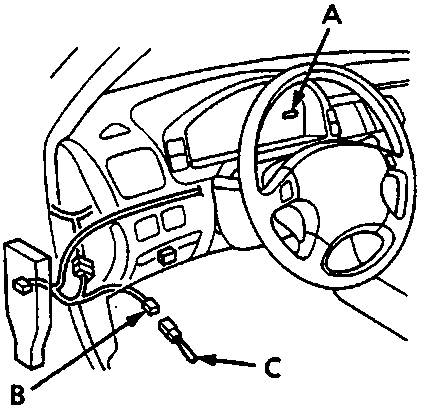
- SRS indicator light
- Memory erase signal (MES) 2 – P connector
- SCS short connector – SMD 4086
- Turn ignition OFF and disconnect the short connector from the service check connector.
- Connect the SCS short connector to the Memory Erase Signal (MES) connector.
- Switch ignition ON (II)
- The SRS indicator light will come on for about 6 seconds and go off. Remove the short connector from the MES connector within 4 seconds after the SRS indicator light went off.
- The SRS indicator light comes on again. Reconnect short connector to the MES connector within 4 seconds after the SRS indicator light coming on.
- The SRS indicator light goes off. Remove the short connector from the MES connector within 4 seconds.
- The SRS indicator light blinks twice to indicate that the memory has been erased.
Parts & tools for this job For Rover 600
- TOOLOBD2 scanner with SRSSearch: OBD2 scanner ABS SRS
- TOOLTrim removal tool kitSearch: trim removal tool kit
Links open Amazon search results in a new tab. As an Amazon Associate I earn from qualifying purchases.