
Components (page 2 of 3)
- Make
- Rover
- Model
- 600 Rover 600 Repair Manual - Volumes 1 and 2 - 2nd Edition
- Section
- Repairs
SuspensionComponents · page 2 of 3
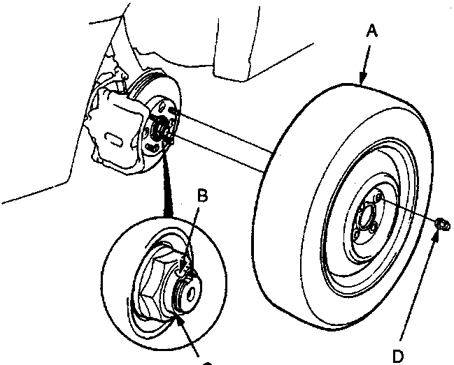
- Front wheel
- Locking tab
- Spindle nut
- Wheel nut
- Raise the locking tab on the spindle nut, then remove the nut.
- Loosen the wheel nuts slightly.
- Raise front of vehicle.
WARNING: Support on safety stands.
- Remove road wheel(s).
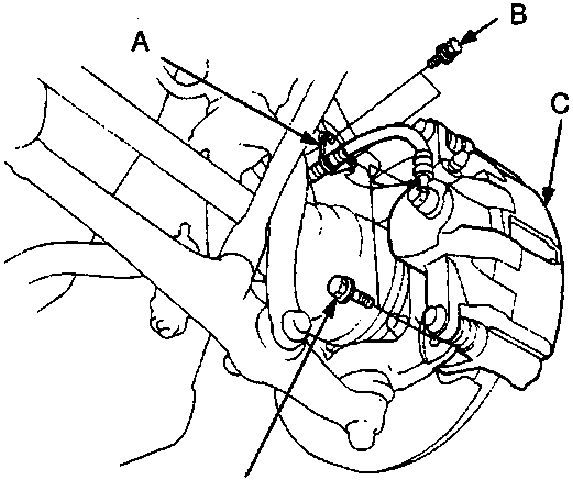
- Brake hose bracket
- Brake hose mounting bolt
- Caliper
- Caliper bracket mounting bolt
- Remove the mounting bolt securing the brake hose bracket.
- Remove the caliper bracket mounting bolts and suspend the caliper on one side.
CAUTION: To prevent accidental damage to the caliper or brake hose, use a short piece of wire to suspend the caliper.
- Remove the wheel sensor wire bracket, then remove the wheel sensor from the knuckle.
Note: Do not disconnect the wheel sensor wire.
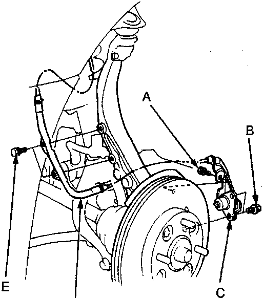
- 6 mm bolt
- Sensor mounting bolts
- Wheel sensor
- Wheel sensor wire bracket
- 6 mm bolts
- Clean any dirt or grease off the ball joint.
- Remove the cotter pin from the castle nut and remove the nut.
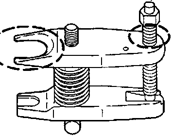
- Pressure bolt
- Apply grease to special tool on the dotted areas shown. This will ease installation of the tool and prevent damage to the pressure bolt threads.
Parts & tools for this job For Rover 600
- TOOLCoil spring compressorSearch: coil spring compressor
- TOOLBall joint separatorSearch: ball joint separator
- PARTShock absorbersSearch: Rover 600 shock absorbers
Links open Amazon search results in a new tab. As an Amazon Associate I earn from qualifying purchases.