
Cylinder head inspection (page 5 of 9)
- Make
- Rover
- Model
- 600 620 Diesel Repair Manual Supplement
- Year
- 1995–1999
- Section
- Repairs
EngineCylinder head inspection · page 5 of 9
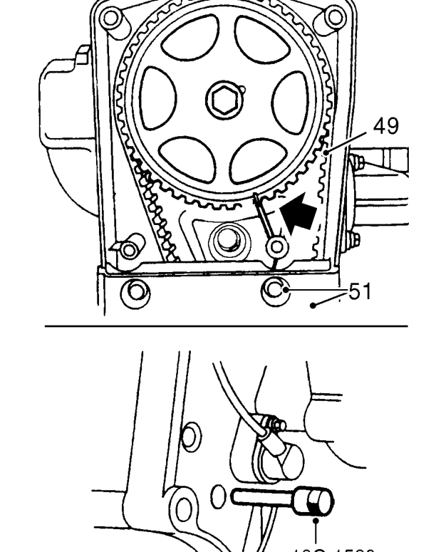
- Ensure timing pin 18G 1523 is fully inserted in hole in flywheel and camshaft gear timing mark is aligned with mark on back cover.
- Ensure locking pin 18G 1717 is inserted in holes in injection pump gear and gearbox mounting plate.
- Using fingers only, fit camshaft timing belt to gears. Ensure the belt run between the crankshaft and camshaft gears is kept taut during the fitting procedure.
- Check sealing strips are correctly located in timing belt lower cover.
- Fit lower cover, fit bolts and tighten to 5 Nm.
- Clean crankshaft pulley and mating face.
- Fit crankshaft pulley, fit bolt and tighten to 63 Nm + 90° .
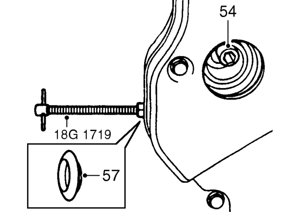
- Loosen tensioner pulley Allen bolt until tensioner moves easily without tipping.
- Release camshaft timing belt tensioner plunger using 18G 1719.
- Remove tool 18G 1719 from camshaft timing belt tensioner and tighten Allen bolt to 55 Nm.
CAUTION: Do not exceed specified torque.
- Fit access plug to timing belt rear cover.
- Remove timing pin 18G 1523 from flywheel.
Parts & tools for this job For 1995 Rover 600
- PARTEngine gasket setSearch: Rover 600 1995 engine gasket set
- TOOLTorque wrenchSearch: 3/8 inch torque wrench
- TOOLFeeler gauge setSearch: feeler gauge set
Links open Amazon search results in a new tab. As an Amazon Associate I earn from qualifying purchases.