
Condenser fan motor – 2.0
- Make
- Rover
- Model
- Coupé, Cabriolet & Tourer 200/400 Coupé, Cabriolet & Tourer Workshop Manual
- Section
- Repairs › Condenser fan motor – 2.0
Air conditioningCondenser fan motor – 2.0 · page 1 of 2
- Fit and tighten 2 bolts, intake pipe to bonnet platform.
- Connect header tank hose to air intake pipe.
- Fit underbelly panel, see BODY – Repairs.
- Remove stands and lower vehicle.
CONDENSER FAN MOTOR – 2.0
Service Repair No. 82.15.01
Remove
- Disconnect battery earth lead.
- Remove front bumper assembly, see BODY – Repairs
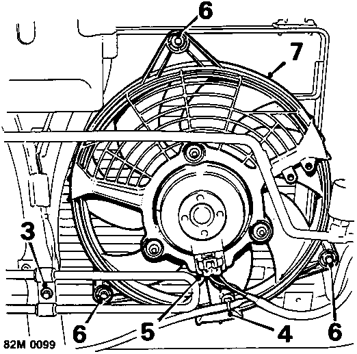
- Remove bolt securing power steering cooler bracket to bonnet platform.
- Release fan motor harness clip from fan cowl.
- Disconnect condenser fan multiplug.
- Remove 3 bolts securing condenser fan cowl to condenser frame.
- Remove fan and cowl assembly.
Refit
- Position fan and cowl assembly, fit and tighten bolts to 10 Nm.
- Connect multiplug and clip harness to fan cowl.
- Fit bolt securing power steering cooler bracket to bonnet platform.
- Fit front bumper assembly, see BODY – Repairs
- Connect battery earth lead.
RELAY MODULE – 1.4 AND 2.0
Service Repair No. 82.20.01
Remove
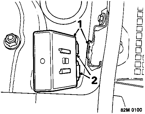
- Release relay module from mounting bracket.
- Disconnect 2 multiplugs from relay module.
- Remove relay module.
Refit
- Connect multiplugs to relay module.
- Fit relay module to mounting bracket.
AIR CONDITIONING RELAYS – 1.6
Service Repair No. 82.20.51
Remove
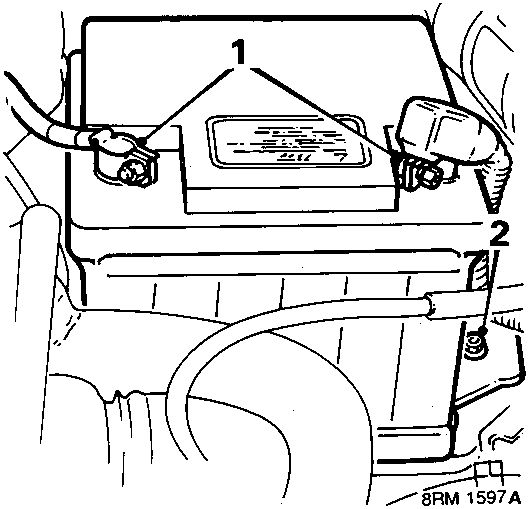
- Disconnect both battery leads.
- Remove bolt and battery clamp and lift out battery.
Parts & tools for this job For Rover Coupé, Cabriolet & Tourer
- TOOLA/C manifold gauge setSearch: AC manifold gauge set
- TOOLUV leak detection kitSearch: AC UV leak detection kit
- PARTCabin filterSearch: Rover Coupé, Cabriolet & Tourer cabin filter
Links open Amazon search results in a new tab. As an Amazon Associate I earn from qualifying purchases.