
Auto
- Make
- Rover
- Model
- Coupé, Cabriolet & Tourer 200/400 Coupé, Cabriolet & Tourer Workshop Manual
- Section
- Repairs › Auto
Engine 1.6Auto
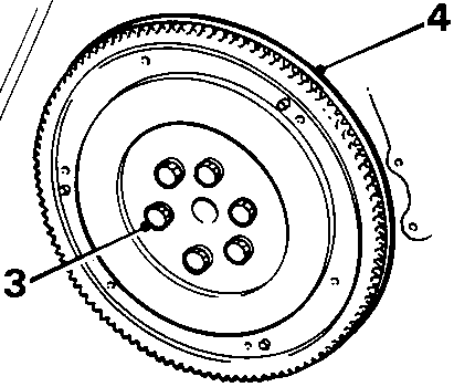
AUTO
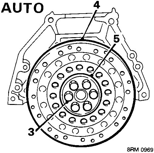
- Remove 6 bolts retaining flywheel/drive plate.
- Remove flywheel/drive plate.
- Recover drive plate bolt lock washer.
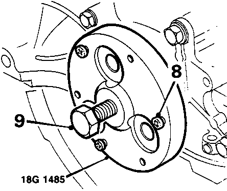
- Fit tool 18G 1485 to crankshaft.
- Punch or drill three pilot holes in seal using holes in tool 18G 1485 as a template.
CAUTION: Use a hand brace when drilling holes; do not allow drill bit to penetrate seal housing.
- Fit 3 self – tapping screws into pilot holes.
- Tighten centre bolt of tool 18G 1485 and extract oil seal; discard seal.
Refit
- Thoroughly clean oil seal recess and end of crankshaft.
- Smear running surface of seal and crankshaft with clean engine oil.
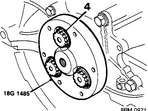
- Locate seal on crankshaft with part number etched on seal facing outwards.
- Locate tool 18G 1485 on crankshaft and fit three bolts to secure tool to flywheel/drive plate boss of crankshaft.
- Tighten each bolt progressively to press seal into recess.
- Remove tool 18G 1485.
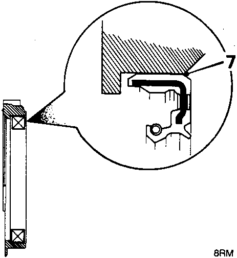
- Check that, when fitted, chamfer of seal is in line with inner edge of seal housing.
- Fit flywheel/drive plate ensuring correct location of dowels.
- Fit 6 flywheel/drive plate securing bolts, tighten flywheel bolts to 120 Nm; tighten drive plate bolts to 75 Nm.
CAUTION: Use a new lock washer for drive plate securing bolts
- Remove tool 18G 1571 or tool 18G 1603.
- Fit clutch plate, see CLUTCH – Repairs.
Parts & tools for this job For Rover Coupé, Cabriolet & Tourer
- PARTEngine gasket setSearch: Rover Coupé, Cabriolet & Tourer engine gasket set
- TOOLTorque wrenchSearch: 3/8 inch torque wrench
- TOOLFeeler gauge setSearch: feeler gauge set
Links open Amazon search results in a new tab. As an Amazon Associate I earn from qualifying purchases.