
Refit
- Make
- Rover
- Model
- Coupé, Cabriolet & Tourer 200/400 Coupé, Cabriolet & Tourer Workshop Manual
- Section
- Repairs › Refit
Engine 1.6Refit
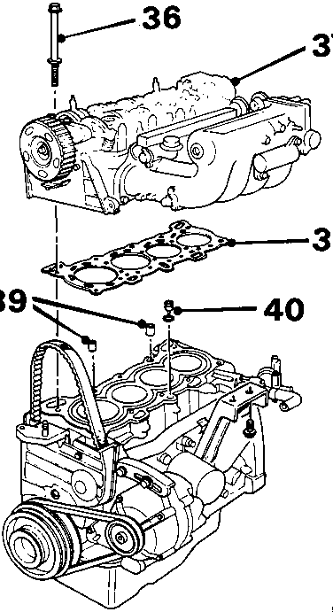
8RM 1559
- Remove bolts and special washers.
- Lift off cylinder head together with manifolds.
- Remove and discard gasket.
- Check that 2 locating dowels are in position in cylinder block.
- Remove oil control jet and 'O' ring; discard 'O' ring.
Refit
- Thoroughly clean cylinder head and cylinder block mating surfaces.
- Ensure locating dowels are in cylinder block.
- Fit a new 'O' ring; fit oil control jet in cylinder block.
- Position new gasket on cylinder block.
CAUTION: Gasket must be fitted dry.
- Ensure 'UP' mark on camshaft pulley is at the top (T.D.C.) position.
- Using assistance, carefully lower cylinder head on to cylinder block ensuring that dowels are correctly located in head.
- Ensure cylinder head bolts are clean.
- Apply clean engine oil to each cylinder head bolt and to the special washers.
- Fit each cylinder head bolt and special washer and tighten finger tight only.
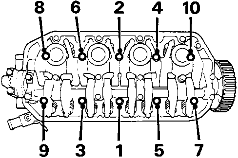
- Working in the order shown, tighten each cylinder head bolt in two stages:
Stage 1 to 30 Nm
Stage 2 to 65 Nm - Fit and tension camshaft timing belt.
- Connect exhaust front pipe, see MANIFOLD & EXHAUST – Repairs.
- Position wiring harness to fuel rail and inlet manifold.
- Connect 4 multiplugs to injectors.
- Fit 2 nuts and bolt to secure cover and harness; tighten nuts and bolt to 22 Nm.
- Fit 2 bolts securing inlet manifold to support bracket; tighten bolts to 22 Nm.
- Connect fast idle multiplug.
- Secure multiplug to bracket on inlet manifold.
- Manual gearbox: Connect 2 reverse lamp switch leads.
- Connect 2 distributor multiplugs.
- Secure distributor multiplugs in retaining clips.
- Connect multiplug to throttle angle sensor.
- Connect T.A. sensor multiplug to inlet manifold.
- Connect 2 coolant sensor multiplugs at cylinder head.
- Connect air cleaner and MAP sensor hoses to inlet manifold.
- Connect P.C.V. hose to inlet manifold.
- Connect thermostat housing to inlet manifold hose; locate 2 clips.
- Connect heater hoses tighten clip.
- Connect top hose; tighten clip.
- Automatic gearbox: Connect throttle control cable to lever.
- Automatic gearbox: Tighten nut on throttle control cable.
- Connect throttle cable and tighten locknut.
- Connect fuel return hose to fuel rail; tighten clip.
- Connect fuel outlet pipe to fuel filter; use new sealing washers.
- Connect brake servo hose to inlet manifold; tighten clip.
- Fit camshaft cover, see Camshaft cover gasket.
8RM 1560
Parts & tools for this job For Rover Coupé, Cabriolet & Tourer
- PARTEngine gasket setSearch: Rover Coupé, Cabriolet & Tourer engine gasket set
- TOOLTorque wrenchSearch: 3/8 inch torque wrench
- TOOLFeeler gauge setSearch: feeler gauge set
Links open Amazon search results in a new tab. As an Amazon Associate I earn from qualifying purchases.