
Refit
- Make
- Rover
- Model
- Coupé, Cabriolet & Tourer 200/400 Coupé, Cabriolet & Tourer Workshop Manual
- Section
- Repairs › Refit
Engine 1.6Refit · page 1 of 2
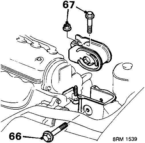
- Remove through bolt, L.H. engine mounting to body.
- Remove 1 bolt and nut, L.H. mounting bracket to cylinder block and remove mounting.
- Raise engine and gearbox and manoeuvre clear of engine compartment.
CAUTION: Ensure lifting chains do not contact camshaft cover.
Refit
- Attach lifting chains to engine and gearbox brackets, lower engine and gearbox into position ensuring that front mounting bracket is aligned to gearbox.
CAUTION: Ensure lifting chains do not contact camshaft cover.
- Fit L.H. mounting, tighten bolts to 55 Nm. Fit through bolt and washer, do not tighten.
- Align front mounting bracket to gearbox; tighten bolts to 55 Nm. Fit NEW through bolt and washer, do not tighten.
- Fit R.H. mounting plate, tighten bolts to 55 Nm. Fit through bolt and washer, do not tighten.
- Align rear mounting bracket to gearbox; tighten bolts to 55 Nm. Fit NEW through bolt, do not tighten.
- Finally tighten mounting through bolts as follows:
Rear mounting to 60 Nm.
Front mounting to 60 Nm.
R.H. mounting to 60 Nm.
L.H. mounting to 55 Nm. - Disconnect lifting chains from brackets.
- Remove engine lifting bracket and spacer.
- Connect L.H. drive to intermediate shaft, see AUTOMATIC GEARBOX 1.6 – Repairs – Differential oil seal – L.H.
- Connect R.H. drive shaft to differential, see AUTOMATIC GEARBOX 1.6 – Repairs – Differential oil seal – R.H.
- Fit starter motor, see ELECTRICAL – Repairs.
- Connect L.H. engine harness at multiplugs.
- Secure harness multiplugs to brackets.
- Connect vacuum pipes to inlet manifold.
- Connect brake servo vacuum hose to pipe.
- Air conditioning: Secure pipe to clip.
- Connect selector cable to lever, fit control pin and roller; secure roller with new split pin.
- Fit torque converter housing cover and anti – bearing bracket; tighten bolts to: 3 bolts – torque converter housing cover bolts 12 Nm.
Anti – bearing bracket to gearbox 45 Nm.
2 bolts – anti – bearing bracket to cylinder block 24 Nm. - Fit selector cable holder, locate cable in holder; tighten bolt to 27 Nm.
- Fit front exhaust pipe, see MANIFOLD & EXHAUST – Repairs.
- Connect speedometer cable to gearbox, secure retaining clip by rotating gaiter.
- Connect hoses to oil cooler pipes, tighten clips.
- Connect 2 heater hoses; tighten clips.
- Connect coolant hoses to engine; tighten clips.
Air conditioning
- Locate compressor and fit securing bolts tighten to 25 Nm.
- Fit and tension compressor drive belt, see MAINTENANCE.
Power steering
- Locate power steering pump and fit securing bolts, tighten to 35 Nm.
- Locate power steering hose in clip.
- Position power steering pipe clamp; tighten bolt to 15 Nm.
- Fit and tension power steering pump drive belt, see MAINTENANCE.
All models
- Connect throttle cable to linkage and locate abutment bracket.
- Secure throttle cable in retaining clips.
- Adjust cable free – play, see ENGINE MANAGEMENT SYSTEM – PGM – Fi – Adjustments.
- Fit distributor, see ENGINE MANAGEMENT SYSTEM PGM – Fi – Repairs.
- Connect fuel outlet pipe to filter, tighten banjo bolt to 32 Nm.
- Connect earth lead to gearbox; tighten nut to 35 Nm.
- Fit battery lead to fusebox and tighten screw, fit fuse cover plate and fusebox cover.
- Connect R.H. engine harness at multiplugs and secure harness with strap.
- Fit battery tray, tighten bolts to 9 Nm.
Parts & tools for this job For Rover Coupé, Cabriolet & Tourer
- PARTEngine gasket setSearch: Rover Coupé, Cabriolet & Tourer engine gasket set
- TOOLTorque wrenchSearch: 3/8 inch torque wrench
- TOOLFeeler gauge setSearch: feeler gauge set
Links open Amazon search results in a new tab. As an Amazon Associate I earn from qualifying purchases.