
Power steering (page 3 of 3)
- Make
- Rover
- Model
- Coupé, Cabriolet & Tourer 200/400 Coupé, Cabriolet & Tourer Workshop Manual
- Section
- Repairs
Engine 1.6Power steering · page 3 of 3
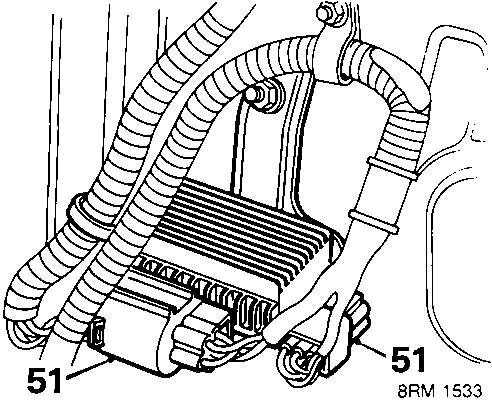
- Release 2 engine harness multiplugs from retaining brackets.
- Disconnect engine harness at 2 multiplugs.
- Release L.H. drive shaft from intermediate shaft, see AUTOMATIC GEARBOX – 1.6 – Repairs – Differential oil seal – L.H.
- Release R.H. drive shaft from differential, see AUTOMATIC GEARBOX – 1.6 – Repairs – Differential oil seal – R.H.
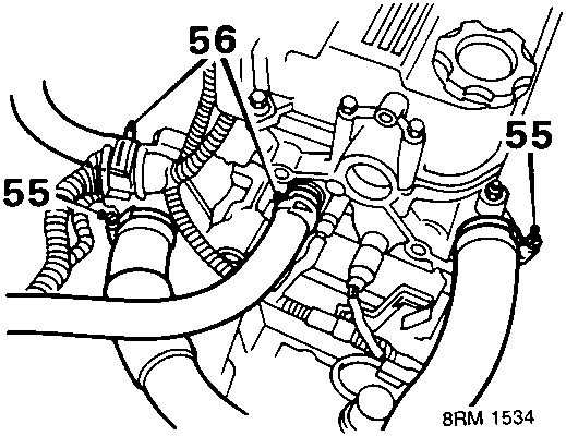
- Slacken clips, disconnect coolant top and bottom hoses from engine.
- Release 2 clips, disconnect heater hoses from engine.
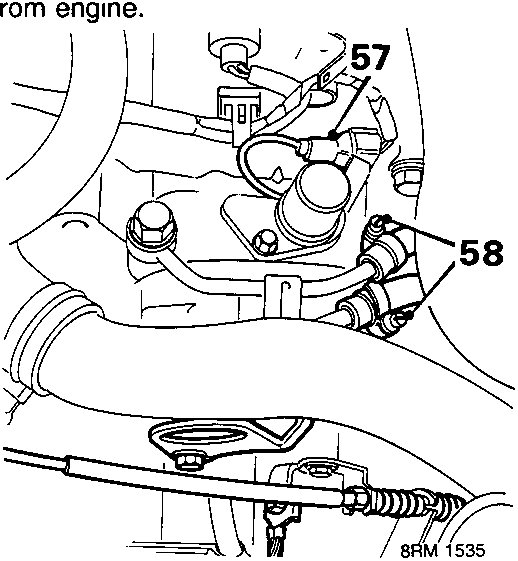
- Disconnect lock – up control solenoid valve multiplug.
- Slacken 2 clips, disconnect oil cooler hoses from pipes.
CAUTION: Plug the connections.
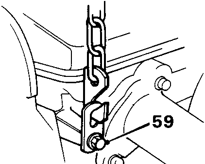
- Fit lifting bracket to cylinder head with a 20 mm thick spacer under a 10 mm bolt, tighten to 30 Nm.
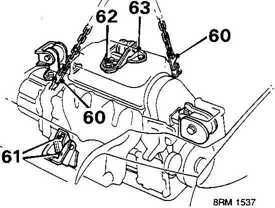
- Connect lifting chains to engine and gearbox brackets and support weight of engine.
- Remove 2 bolts, front mounting to body.
CAUTION: Do not slacken front mounting through bolt.
- Remove 3 bolts, rear mounting bracket to gearbox bracket.
- Slacken rear mounting through bolt, raise mounting bracket clear of gearbox.
- Remove through bolt R.H. mounting to body.
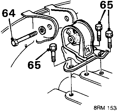
- Remove 3 bolts, R.H. mounting plate to gearbox and remove mounting.
Parts & tools for this job For Rover Coupé, Cabriolet & Tourer
- TOOLTie rod end toolSearch: tie rod end puller
- TOOLBall joint separatorSearch: ball joint separator
- FLUIDPower steering fluidSearch: Rover power steering fluid
Links open Amazon search results in a new tab. As an Amazon Associate I earn from qualifying purchases.