
Fuel tank and components
- Make
- Fiat
- Model
- 500 Factory Service Manual
- Year
- 2007–2024
- Section
- Fuel tank and pipes › Fuel tank and components
FUEL TANK AND COMPONENTS
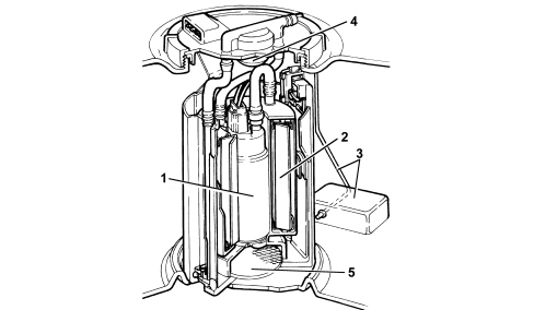
SUMBERGED PUMP ASSEMBLY - COMPOSITION
It consists essentially of:
- an electric fuel pump (1)
- a fuel filter (2)
- a float level level gauge (3)
- a pressure regulator (4)
- a mesh prefilter (5).
Level gauge electrical values
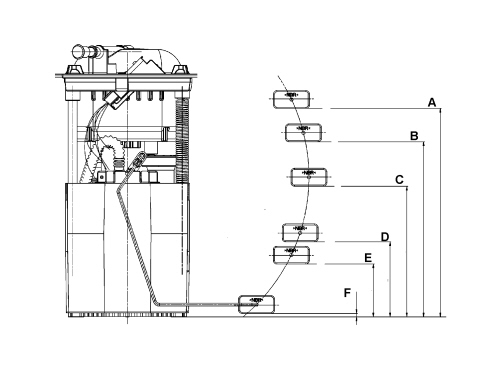
| Reading on multiple instrument | Resistance (Ohm) | Fuel level (mm) | Lower float edge height (mm) | |
|---|---|---|---|---|
| 4/4 | A | 33 ± 3 | 195 | 186,4 ± 2 |
| 3/4 | B | 76 ± 3 | 165 | 156,6 ± 2 |
| 1/2 | C | 134 ± 3 | 125 | 116,9 ± 2 |
| 1/4 | D | 206 ± 3 | 75 | 67,1 ± 2 |
| R | E | 235 ± 3 | 55 | 47,2 ± 2 |
| 0 | F | 299 + 3,5 / -3,3 | 10,5 | 3 ± 2 |
The fuel pump connector is illustrated in the diagram below.
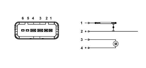
1. Level sensor signal
2. Level sensor earth
3. Pump earth
4. Pump signal
5. N.C.
6. N.C.
Fuel pump
The fuel pump is equipped with a permanent magnet electric motor (1) that controls the pump (2) and a terminal mount cover (3) that contains the electrical and hydraulic connections.
The pump stage is single, peripheral flow type with high performance under low voltage and temperature conditions.
The advantages compared to pumps that operate on volumetric principles are as follows:
- reduced weight
- limited size.
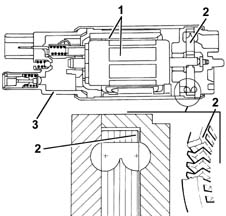
Fuel pump
Specifications:
- Capacity = 80 l/h
- Pressure 4 bar
- Valve control pressure = 5 bar
Fuel cut off function
There is no inertia switch on this vehicle; the fuel cut off function is managed by the Body Computer Node and by the Engine Management Control Unit according to the signals received by the Air Bag control unit via the CAN.
For more details see
See descriptions 1056 PETROL INJECTION SYSTEM
SUBMERGED PUMP ASSEMBLY COMPLETE WITH LEVEL GAUGE
The fuel pump is part of a single assembly with the level gauge and fuel filter. Components cannot therefore be replaced individually.
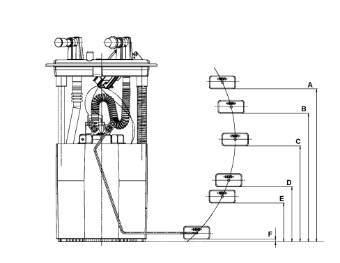
Level gauge electrical values
| Reading on multiple instrument | Resistance (Ohm) | Fuel level (mm) | Lower float edge height (mm) | |
|---|---|---|---|---|
| 4/4 | A | 33 ± 3 | 195 | 186,4 ± 2 |
| 3/4 | B | 76 ± 3 | 165 | 156,6 ± 2 |
| 1/2 | C | 134 ± 3 | 125 | 116,9 ± 2 |
| 1/4 | D | 206 ± 3 | 75 | 67,1 ± 2 |
| R | E | 235 ± 3 | 55 | 47,2 ± 2 |
| 0 | F | 299 + 3,5 / -3,3 | 10,5 | 3 ± 2 |
FUEL PUMP
The fuel pump is equipped with a permanent magnet electric motor (1) that controls the pump (2) and a terminal mount cover (3) that contains the electrical and hydraulic connections.
The pump stage is single, peripheral flow type with high performance under low voltage and temperature conditions.
The advantages compared to pumps that operate on volumetric principles are as follows:
- reduced weight;
- limited size.
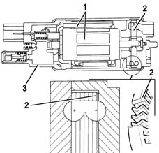
Pump working point
The pump specifications are described below:
- Capacity: = 135 l/h
- Pressure: 2.6 bar
- Supply current: 12.5V
- Valve control pressure: between 5 bar and 8.5 bar
Fuel cut off function
There is no inertia switch on this vehicle; the fuel cut off function is managed by the Body Computer Node and by the Engine Management Control Unit according to the signals received by the Air Bag control unit via the CAN.
For more details see
Parts & tools for this job For 2007 Fiat 500
- PARTEngine gasket setSearch: Fiat 500 2007 engine gasket set
- TOOLTorque wrenchSearch: 3/8 inch torque wrench
- TOOLFeeler gauge setSearch: feeler gauge set
Links open Amazon search results in a new tab. As an Amazon Associate I earn from qualifying purchases.