
Horns - wiring diagram
- Make
- Fiat
- Model
- Bravo Factory Service Manual
- Year
- 2007–2014
- Section
- Electrically activated devices › Horns - wiring diagram
Wiring diagrams and electrical functionsHorns - wiring diagram
HORNS - WIRING DIAGRAM
WIRING DIAGRAM
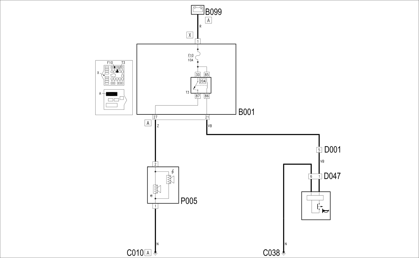
COMPONENTS
| Component code | Description | Reference to the operation |
|---|---|---|
| B001 | JUNCTION UNIT | Op. 5505A13 ADDITIONAL JUNCTION UNIT IN ENGINE COMPARTMENT - R.R. |
| B099 | MAXI FUSE BOX ON BATTERY | |
| C010 | LEFT FRONT EARTH | |
| C038 | EARTH ON CENTRE TUNNEL | |
| D001 | FRONT/DASHBOARD COUPLING | |
| D047 | CLOCK SPRING COUPLING | Op. 5550A10 STALK UNIT ASSEMBLY - R+R |
| M001 | BODY COMPUTER | Op. 5505A35 MAIN BODY COMPUTER/JUNCTION UNIT - R.R. |
| P005 | SINGLE-TONE HORN | Op. 5550B30 L/H OR R/H HORN (ONE) - R+R |
Parts & tools for this job For 2007 Fiat Bravo
- PARTReplacement bulbsSearch: Fiat Bravo 2007 bulbs
- TOOLDigital multimeterSearch: automotive digital multimeter
Links open Amazon search results in a new tab. As an Amazon Associate I earn from qualifying purchases.